Auto binds to pairing device
gampad activity shows here
and see serial monitoring
for more devices & info
Auto binds to pairing device
gampad activity shows here
and see serial monitoring
for more devices & info
This is an alternative take on the previous article Adafruit ST7789 TFT display with Arduino GFX Library and M5StampS3. This time with a generic display, and a different MCU (ESP32-C3). This one has a single RISC-V core (instead of dual core Xtensa).
So excuse the repeated text, the content has been changed only slightly for the different hardware...
Attaching a display to a circuit can provide a lot of detailed info and graphical value. While "a picture is worth a thousand words," an animated display can be entertainment value, textual information can be informative, and add an input device, and the system can be interactive with billions of possibilities.
The tricks in embedded development is choosing the right display, having the right library that supports the display, and figuring out to use it all together with your target embedded system.
Shown above is a minimal footprint ESP32-C3 development board (I purchased one from AliExpress for around two US dollars, very cheap!), with a generic IPS 240x240 TFT display (ST7789 based) I had purchased years ago on eBay. An SPI interface is utilized for communications using the GFX Library for Arduino. I am using a solderless breadboard to prototype the circuit. Later I will implement as a more permanent circuit.
Besides power and ground, there are only 4 connections from the ESP32: SCLK, MOSI, DC, and Reset. In this sample, the TFT select line is permanently selected by connecting to ground.
Attaching a display to a circuit can provide a lot of detailed info and graphical value. While "a picture is worth a thousand words," an animated display can be entertainment value, textual information can be informative, and add an input device, and the system can be interactive with billions of possibilities.
The tricks in embedded development is choosing the right display, having the right library that supports the display, and figuring out to use it all together with your target embedded system.
Shown above is a minimal footprint ESP32S3 in the form of an M5StampS3 from M5Stack connected to 2.54mm pins, with a rounded corner ST7789 based 280x240 display from Adafruit. An SPI interface is utilized for communications using the GFX Library for Arduino. I am using a solderless breadboard to prototype the circuit. Later I will implement as a more permanent circuit.
Besides power and ground, there are only 4 connections from the ESP32: SCLK, MOSI, DC, and Reset. In this sample, the TFT select line is permanently selected by connecting to ground.
(The Adafruit display used in this example also includes a MicroSD connector and SPI connections for that as well. Support for SD is beyond the scope of this article, and would require additional changes to the circuit and code.)
This "portable" Commodore 64 and 128 emulator (m5 source code branch) is my work in progress, one in a series of minimalist emulators ported to different hardware targets. Only text (on LCD) with background, foreground, border colors, keyboard entry via USB serial tethered web browser, and general 6502/6510 and C64 memory management emulation is present (no, won't play games, make sound, or do bitmapped graphics) with some D64 emulation [added 7/2/2023].
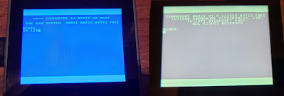
(Update 7/28/2023) Now with GO 128 command.
![]() |
| GO 128 command |
Even my son asked, "Why do you need to do that?" Well, he has a point. I wanted a C64 that fit in my pocket or even on my wrist. And targeting new hardware platforms with my emulator is part of my hobby.
How does it work? Check out my highly technical drawing.
Now I already here you asking why I didn't connect Bluetooth to the M5Core, because certainly it has Bluetooth as well, and why didn't I use a USB keyboard connected to CoreS3, because it includes USB Host. But I've had trouble tracking down examples of HID Host examples for M5; client examples are prevalent, but host?
Pictured here is a phone is running Chrome with a custom copy of the html/javascript keyboard adapter including web-serial-polyfill because mobile Chrome doesn't directly include Serial API support. A Palm Pilot foldable keyboard has a Bluetooth adapter, paired with the phone. HID keystrokes are captured by the web page, converted to C64 key scan codes, and a list of the active key scan codes (or 64 when keys released) is sent over USB Serial to the M5Core device which is running the C64 ROMs which are tricked into thinking a real keyboard is attached; keystrokes are processed by the C64 KERNAL IRQ as normal.
The M5Core is being powered by the phone. Why M5Core? Because it's a polished packaged solution.
Yeah, we could just run a Commodore 64 emulator on the phone, but this way, I could have complete control over the keyboard emulation, what keys are present, how CTRL and Commodore keys work, etc. And it's just because I can, not because I should.
Why the Palm Keyboard? Because it folds in my pocket! And because I had one from back in the day. Any keyboard you can attach to a phone or computer should work. And this Bluetooth adapter just makes it so cool, and easier than a tethered keyboard.
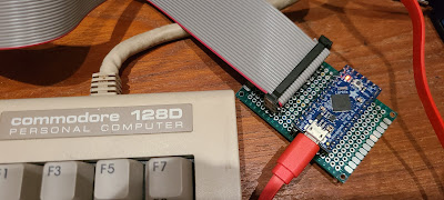
The next step is to merge this solution with my Commodore 128 keyboard adapter to completely reject the portability feature. That would look really cool hooked up to my phone! Update (7/31/2023): check out YouTube for connection from ItsyBitsy/keyboard to Core Port.A.
![]() | ||
C128 Keyboard Adapter Breadboarded Prototype
|
I am excited about my nonsense crazy adventures. Even if only I enjoy them.
=====
Update (7/2/2023): D64 support is currently working with Core2 only (Basic Core doesn't usually have the additional SPI RAM, but not yet sure why CoreS3 is failing to attach SD).
Update (7/3/2023): Got CoreS3 working with SD switching header to M5Unified.h for that target (was M5Cores3.h) and adding special definition, override logic for SD_CS to use GPIO_NUM_4 instead of default. See updates to M5Core.h.
Update (7/28/2023): Commodore 128D extended keyboard working with UART connection to Port.A of Core, and Commodore 128 emulation is ported as well.
=====
I have developed a number of prototype shields for Arduino using a ProtoShield that have been compatible with my various Arduinos, Netduinos, and other development boards providing plug compatibility with Arduino shields. With the addition of the new R3 pins: SCL, SDA, IOREF some more platform independence has occurred allowing the shield (or at least its I/O) to run at the same voltage as the target platform, and a standardization of the location of the I2C pins. The SPI pins which were originally reserved for ICSP or initial programming of the Arduino also became a standard. I opted to skip the SPI/ICSP pin compatibility and stick with the Uno SPI pin layout for simplicity; a future version should include the SPI/ICSP pins in their expected location. An R3 version of the ProtoShield was found here and I had seeedstudio build the PCBs.
Standard height 0.45" header pins were used to connect the ProtoShield to the above mbed adapter. The above mbed adapter used taller 0.7" header pins so the PCB barely clears the height of the mbed, only touching the mini USB socket. Since my prototyping boards have solder terminals only on one side, and to keep them clean looking I try to solder only on the bottom, hidden from view, I used needle nose pliers to push the pins so the plastic is flush with the top of the pins, and then carefully solder the pins from the bottom of the board not getting them too hot or the pin could waver out of place. Once all the pins are soldered into place they hold very securely.
All the available pins on the mbed are either connected to the Arduino headers, or a few are broken out for additional expansion: since the workshop board already uses pins 5-8, they were left as an expansion; CAN and battery lines are implemented as jumpers for expansion. Analog pins and power pins are where they should be, one UART is wired to D0/D1 for Arduino compatibility, and one SPI is wired for original Uno compatibility (D13-D10). One pair of I2C pins are in the new R3 location, and the same pins are also wired to the same location as done with the Leonardo: D2/D3. The remaining D14 and PWM pins are wired to the remaining Arduino header pins. The schematic below shows how I chose to map the pins between the boards.![]() |
| Schematic - Click on image to view larger |
![]() |
| Schematic |
| Board | Type | VCC | Pullups | SDA/SCL | Solution | Notes |
| Arduino Duemilanove | arduino | 5V | internal | A4/A5 | Wire.h | |
| Arduino Leonardo | arduino | 5V | external | D2/D3 | Wire.h | |
| chipKIT Max32 | arduino | 3.3V | external | D20/D21 | Wire.h | 1 |
| chipKIT Uno32 | arduino | 3.3V | external | A4/A5 | Wire.h | 2 |
| Netduino Mini | netmf | 3.3V | on board | 9/10 | I2CDevice | 3 |
| Netduino Plus | netmf | 3.3V | external | A4/A5 | I2CDevice | |
| Netduino Plus 2 | netmf | 3.3V | external | SDA/SCL | I2CDevice | 4 |
| Panda II | netmf | 3.3V | on board | D2/D3 | I2CDevice | |
| FEZ Cerbuino Bee | netmf | 3.3V | external | D2/D3 | SoftwareI2CBus | 5, 6 |
| Netduino Go Shield Base (Standalone) | netmf | 3.3V | internal | A4/A5 | SoftwareI2C | 7 |
![]() |
| Schematic |
![]() |
| EEPROM Shield Schematic |
| Under belly of the shield |
| Christmas LED Shield |
| Curtain Rod Installation |
| It works! Shown with my thermometer board |
| PIC24FJ64GB002 shown |
| PIC32MX220F032B shown |
| Underbelly |
