Showing posts with label SPI. Show all posts

Sunday, September 15, 2024

No name IPS 240*240 ST7789 TFT display with Arduino GFX Library and ESP32-C3 (RISC-V) development board


This is an alternative take on the previous article Adafruit ST7789 TFT display with Arduino GFX Library and M5StampS3.   This time with a generic display, and a different MCU (ESP32-C3).  This one has a single RISC-V core (instead of dual core Xtensa).

So excuse the repeated text, the content has been changed only slightly for the different hardware...


Attaching a display to a circuit can provide a lot of detailed info and graphical value.  While "a picture is worth a thousand words," an animated display can be entertainment value, textual information can be informative, and add an input device, and the system can be interactive with billions of possibilities.

The tricks in embedded development is choosing the right display, having the right library that supports the display, and figuring out to use it all together with your target embedded system.

Shown above is a minimal footprint ESP32-C3 development board (I purchased one from AliExpress for around two US dollars, very cheap!), with a generic IPS 240x240 TFT display (ST7789 based) I had purchased years ago on eBay.  An SPI interface is utilized for communications using the GFX Library for Arduino.  I am using a solderless breadboard to prototype the circuit.  Later I will implement as a more permanent circuit.

Besides power and ground, there are only 4 connections from the ESP32: SCLK, MOSI, DC, and Reset.  In this sample, the TFT select line is permanently selected by connecting to ground.

#include <Arduino.h>
#include <Arduino_GFX_Library.h>

Arduino_DataBus *bus = new Arduino_HWSPI(6/*dc*/, 7/*cs*/,
   2/*sclk*/, 3/*mosi*/, 10/*miso*/, &SPI,
   true/*is_shared_interface*/);
Arduino_GFX *gfx = new Arduino_ST7789(bus, 11/*rst*/, 1/*r*/,
   true/*ips*/, 240, 240);

void setup() {
  gfx->begin();
  gfx->fillScreen(BLACK);
  gfx->setTextColor(WHITE);
}

void loop() {
  int x = (int)random(240);
  int w = (int)random(240 - x);
  int y = (int)random(240);
  int h = (int)random(240 - y);  
  int color = (int)random(65536);
  gfx->fillRect(x, y, w, h, color);
  if (random(20)==13)
    delay(100);
}

The wiring corresponds to the code of the databus and gfx initialization parameters, specifically lines GPIO02 (SPI CLK), GPIO03 (SPI MOSI), GPOI06, GPIO11 of the ESP32-C3 connected to SCL, SDA, DC, and RES (Reset) of the display respectively.  Also both the VCC and BLK lines of the display are connected to 3V3, and GND is connected commonly between the display and ESP32-C3 board.  MISO and CS lines are defined for use in the code, but wiring them was unnecessary and not possible.

TFT   ESP32-C3
GND   Ground
VCC   3V3
SCL   SPI Clock (2)
SDA   SPI MOSI (3)
RES   (11)
DC    (6)
BLK   3V3

Not sure why triangles are sometimes displayed (maybe out of range data?).  That is why there is a 5% chance of a tenth of a second delay to pause for the viewer.

This is just a demo.  You should be able to find much better uses for the display that these random rectangles.

Build details:
  • Arduino IDE 2.3.2
  • esp32 boards 3.0.4
  • GFX Library for Arduino 1.4.7
Important!  The board I have will only run its flash chip in DIO mode, so be sure to check all the board options in Tools menu of Arduino IDE before flashing, or if you run into trouble.  Also, updating board libraries may reset your options to default so if flashing after a time, check these settings again, and again.

Some models of the ESP32-C3 development board have a serial chip, and some utilize the C3's built in USB support.  Be sure to set USB CDC on Boot settings accordingly, and use the BOOT/RST buttons to put into bootloader mode for flashing if necessary.

I found it necessary to unplug and replug the ESP32-C3 board to get the graphic demo to work.  Your mileage may vary.

Thursday, February 20, 2014

eBible on Cortex M0 with mbed

The eBible code has been ported from to use a Cortex M0 device and external flash chip.  The original chip used an M3 with lots of flash and SRAM, but this M0 part (NXP LPC1114FN28) has only 32Kbytes flash and 4Kbytes SRAM.

The challenge was to reduce and rewrite the functionality using less resources.  The M3 solution had used an SD card with FAT filesystem and had access to 512Kbytes flash and 64Kbytes SRAM.  All that was originally required was the bible.txt file on the SD, and the firmware would index all the books, chapters, and verses for navigation into multiple files on the SD card the first time it ran.  The M3 had no problem loading large sections of the text into memory to parse it into verses.  The M0 with its limited resources has less capability.

The M0 version does not use a file system, so the Bible text and index data are stored sequentially in flash storage (Spansion S25FL164K).  The index data structure is a sequence of structures for books, then intermixed with structures for chapters and verses.  The structures include text offsets, counts, and variable sized arrays pointing to other structures.  A fixed offset to the index structure, and bookmark structure is included in the code.  A separate firmware program for the M3 was written to convert the SD text and indexes and store them in flash.  This program was run once on the M3 to populate the flash chip, then the flash chip was moved to the M0 circuit.

Two different SPI circuits are present with one for the display and one for the flash.  The M0 chip used only has one SPI peripheral, so software SPI (bit banged) was implemented (ported from my C# implementation) to simulate another SPI peripheral.

A Text LCD wrapper library targeting Nokia 5110 was written to reduce the number of changes to the eBible source in porting from a text only lcd to the graphical Nokia 5110 lcd.

The remaining portions of the circuit to mention are the 3.3V voltage regulator (Microchip MCP1702), Nokia 5110 LCD display (purchased on eBay from a seller in Shenzhen, China), two switches, three blue LEDs, three AAA batteries, a battery holder, and some sockets.  A surface mount prototyping adapter board (SO8-50-EB) was used to attach the flash memory.  Two screws secure the battery holder to the circuit board.  The outside LEDs mirror the button presses, and the center LED flashes when bookmarks are changed when holding down both buttons.  Pressing the left button goes back one screen of text, and the right button advances to the next screen of text or next verse whichever comes first.  Holding down the buttons for a time navigates back or forward by multiple verses, chapters, or books depending on how long they are held down.  While navigating large sections of text, the book name, chapter number, and verse number are displayed, then switch back to the text after the buttons are released.

The parts chosen were primarily with consideration of cost.  The memory, display, and microcontroller are mbed online compiler and mbed library.  For debugging, the code was simply exported from the online compiler to Keil uVision 4 using a SeeedStudio Arch to act as the CMSIS-DAP debugger and programmer.  Being able to use a full-featured IDE including debugger for an mbed target is greatly appreciated.  Most of the work was done with the components in a breadboard, then transferred to a solder prototyping breadboard.  The result is a handheld electronic Bible that is smaller and more cost efficient that the originally developed version.
Schematic

Thursday, September 26, 2013

mbedR3uino: mbed adapter for Arduino shields

The mbedR3uino is a vertical shield adapter for the mbed prototyping platform.  It provides compatibility with standard Arduino shields including the pins added to Arduino Uno R3 to make shields more independent between main boards.

This is the project I wanted three years ago.  Finally the need, inspiration, materials, and dependent projects converged.  The ability to easily add pluggable hardware to the mbed had been demonstrated when I created the In-between Shield for mbed which plugged into the mbed workshop board adding flash memory to the mbed which plugged into the shield. 

 
I have developed a number of prototype shields for Arduino using a ProtoShield that have been compatible with my various Arduinos, Netduinos, and other development boards providing plug compatibility with Arduino shields.  With the addition of the new R3 pins: SCL, SDA, IOREF some more platform independence has occurred allowing the shield (or at least its I/O) to run at the same voltage as the target platform, and a standardization of the location of the I2C pins.  The SPI pins which were originally reserved for ICSP or initial programming of the Arduino also became a standard.  I opted to skip the SPI/ICSP pin compatibility and stick with the Uno SPI pin layout for simplicity; a future version should include the SPI/ICSP pins in their expected location.  An R3 version of the ProtoShield was found here and I had seeedstudio build the PCBs.

The mbedR3uino is named because mbeduino was already taken.  Inserting the R3 in the name gives it some uniqueness while expressing its meaning.  The adapter consists of two pluggable pieces.  The first plugs into the workshop board above the mbed providing a footprint identical to the mbed.  Components were added to the ProtoShield to plug it into the first piece, and wire the connections to the Arduino R3 headers.  The result is that Arduino shields can be connected to the mbed.


Standard height 0.45" header pins were used to connect the ProtoShield to the above mbed adapter.  The above mbed adapter used taller 0.7" header pins so the PCB barely clears the height of the mbed, only touching the mini USB socket.  Since my prototyping boards have solder terminals only on one side, and to keep them clean looking I try to solder only on the bottom, hidden from view, I used needle nose pliers to push the pins so the plastic is flush with the top of the pins, and then carefully solder the pins from the bottom of the board not getting them too hot or the pin could waver out of place.  Once all the pins are soldered into place they hold very securely.

Note that the mbed workshop board or equivalent is required.  It already provides SD, Ethernet, and USB connectivity.  I have a revA board which pin 9 is held high to 3.3V (intended for SD card detect?), so to allow it to be used for the UART, I cut the trace on the workshop board.  An alternative to using the workshop board would be to have dual row headers and connect the columns for all pins 1-40, as done in my mbed Text LCD development board.  It is relatively easy to also solder a USB B connector, and an Arduino shield can be used for an SD card.  Connecting an Ethernet jack directly to the mbed can be done using a breakout board.

All the available pins on the mbed are either connected to the Arduino headers, or a few are broken out for additional expansion: since the workshop board already uses pins 5-8, they were left as an expansion; CAN and battery lines are implemented as jumpers for expansion.  Analog pins and power pins are where they should be, one UART is wired to D0/D1 for Arduino compatibility, and one SPI is wired for original Uno compatibility (D13-D10).  One pair of I2C pins are in the new R3 location, and the same pins are also wired to the same location as done with the Leonardo: D2/D3.  The remaining D14 and PWM pins are wired to the remaining Arduino header pins.  The schematic below shows how I chose to map the pins between the boards.

Schematic - Click on image to view larger

Thursday, April 12, 2012

In-between Shield for mbed with 128Mbit Flash


In-between Flash Shield with SST25VF064C
The "In-between Shield" has been developed as a means to extend the attached peripherals of the mbed in a clean looking manner, inspired by the expandability of Arduino, but unique and true to the mbed experience.
This shield is designed to fit and work with the workshop board for mbed.  This is a a breakout board for Ethernet, USB, and SD for mbed.  Instead of the mbed placed in the workshop board, the in-between shield is placed first, and the mbed sits on the shield.  It should be possible to stack additional shields depending on the height of the components on each shield.

The shield itself is composed of a solder breadboard cut to the dimensions of the workshop board, with an additional cutout to avoid the height of the Ethernet jack.  I reduced this board's dimensions further so the USB ports can be visible from above.  This visibility helps with attaching cables and devices.


workshop board
In-between shield
underside
Flash breakout boards


Above board shield in use
The first in-between shield has two 8-pin sockets to accommodate a 16-pin SOIC breakout board with a flash chip attached (SST25VF064C or MX25L12835E).  The flash breakout board can be easily changed out to attach different flash parts. Wiring beneath the shield connects the necessary pins back to the mbed.  The mbed sits in two 2x20 wire wrapping sockets.  No wire wrapping is used in this project.  The advantage to the wire wrapping sockets is the extended leads so the shield sits above the workshop board.

The dual row sockets are used to extend the purpose of the workshop board: each side of the mbed sits in one row, and another row is provided for allowing jumper wires or a single above board shield. The rows of pins are not connected with the shield, it depends on their connections in the workshop board. If the workshop board is not available, a good substitute is another solder breadboard with two 2x20 sockets (short leads), with solder bridges between the pins. 
Solder bridges


The evolution of the flash shield included an ugly do it yourself SOIC to 2x4 pins breakout board made up from two separate 50 mils pitch boards, one for each side of the SOIC chip. An additional board was made to adapt dual 2x4 sockets to a single row 8-pin breadboard friendly connector, with LED to show power. The next iteration was an above mbed board using long single row headers that can be soldered to the bottom of a solder breadboard. Last but not least, the in-between shield was created.

First prototype and breakouts
Above board shield prototype

Source code for this project is posted here. Driver for SST 64Mbit flash (8Mbyte) model 25VF064C including higher level methods for rewrite and buffered read/write to help optimize I/O. Can also work with other 25 series flash and eeprom devices, requiring minor revisions for their capabilities.

The end result of the in-between shield is a clean looking prototype of an mbed connected to a SOIC flash chip that can be further expanded.

Shield shown with MX25L12835E 128Mb Flash

Sunday, March 18, 2012

EEPROM Shield

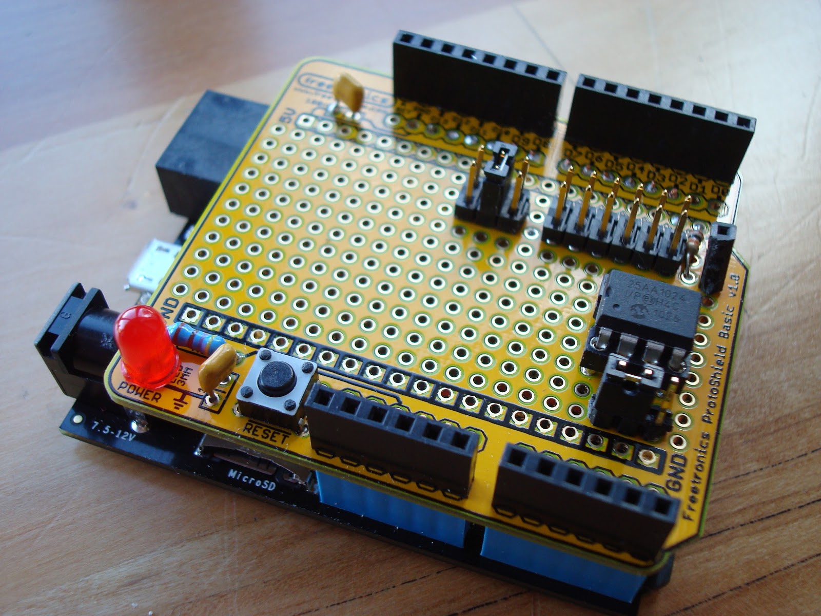
This shield was created to help learn SPI (Serial Peripheral Interface).  The hardware consists of an empty prototype shield for Arduino with a Microchip 25AA1024 EEPROM, jumpers, sockets, LED, switch, and discrete components.

This shield allows an microcontroller to store and retrieve up to 128K bytes of data using SPI at up to 20MHz speed.
The target platform was Microsoft .NET Micro Framework 4.1 as shown mounted on the Netduino Plus, and also demonstrated to work on the FEZ Panda II.  Source code for the project is posted at github in the form of a class library DLL and test application.  Note this code requires Microsoft .NET Micro Framework APIs and will not work on a standard Arduino.  Many others have written libraries for this chip for Arduino and other platforms.

The large array of jumpers allows configuration of the chip select line to one of digital pins 2-10.  The hold pin is pulled high and socketed to allow for future use, but is not wired to any of the microcontroller's pins.  The WP (write protect) pin is jumpered to allow it to be pulled high (disabled) or pulled low (enabled).  The circuit for the LED and reset switch was already present on the prototype shield.

A possible revision to this circuit would be to add a jumper for choosing 3.3V or 5V operation if it needs to be used with a board that is not 5V tolerant.  The boards I used run at 3.3V but are 5V tolerant. 

Future revisions to the source code could include supporting a wider range of EEPROMs from Microchip, SST, and other manufacturers, and/or porting the code to other platforms including mbed, chipKIT, PIC, and Arduino.


EEPROM Shield Schematic
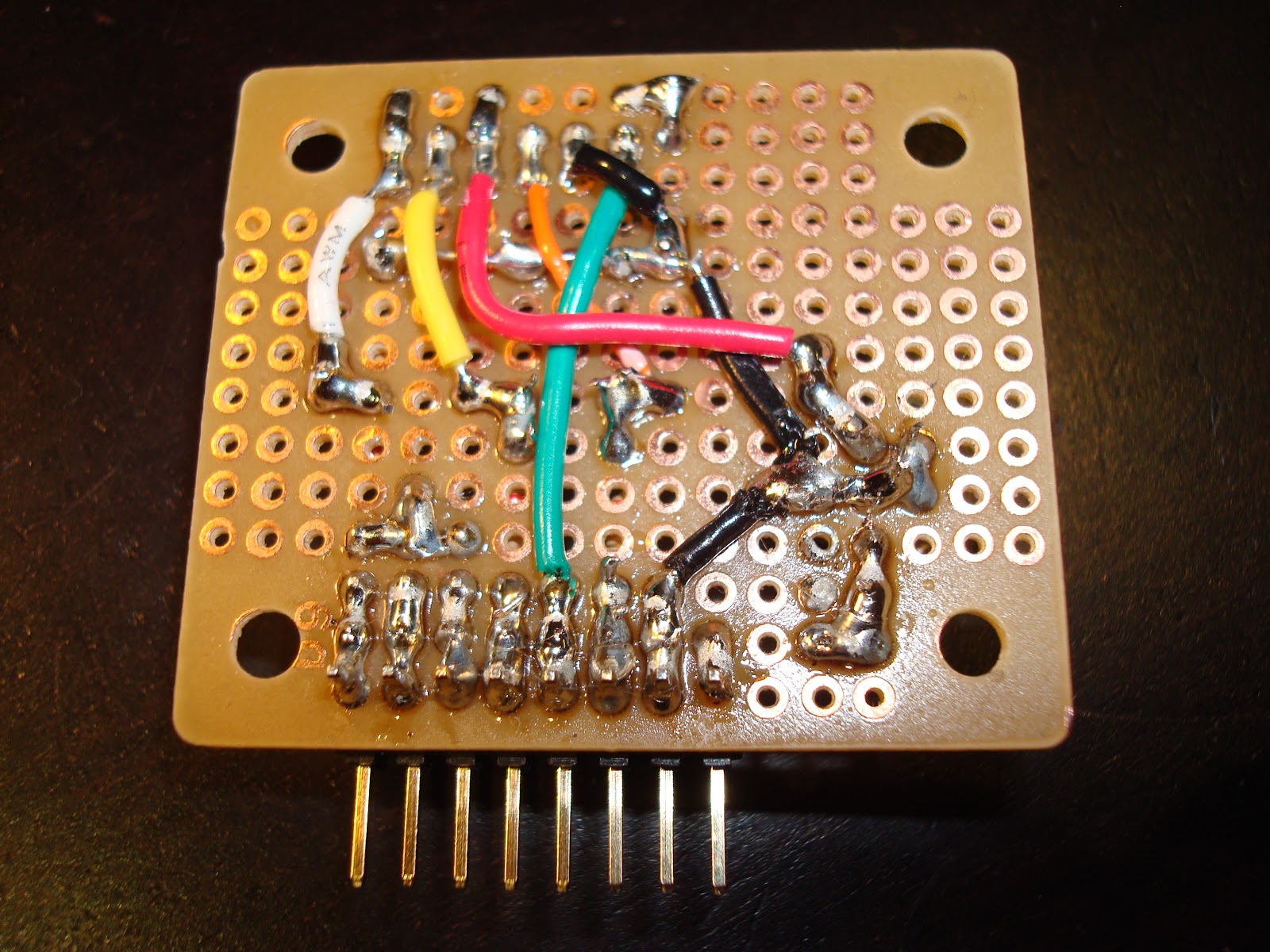
Under belly of the shield

Saturday, September 10, 2011

microSD Arduino adapter

Arduinos are meant to be attached to peripherals.  Here is an adapter from a 5V Arduino to a 3.3V microSD card.  To bridge the gap from circuit board to SD card, a socket is used to connect a microSD breakout board (BOB).  Resistor voltage dividers bridges the gap between the voltage differences for outputs.  A low dropout voltage regulator supplies 3.3V power for the SD card.  Inputs from the SD card are within spec for the Arduino, so they did not have to change.

This adapter is a vertical shield.  It has a socket so the pins are accessible if the attachments are compatible.  It only connects to the AREF to D8 eight position socket, which does not have power, so it requires a jumper from 5V(VCC) to one of the slots on its dual socket, so as to replace the 5V socket with another one.  It also has a 1 port card detect (CD) socket, which can be jumpered to another available pin on the Arduino.

It is modeled to support the SD CardInfo example included in the Arudino IDE.  Chip select (CS) is connected to D8 with a jumper, it can be moved to D9 or D10.  It can be used simultaneously with the Ethernet non-shield.


5V Arduino SD Adapter Schematic

Tuesday, September 6, 2011

My own first PIC32 Development Board

Here is a USB PIC32 development board that is in progress.  I bought a bare 64-pin PIC32MX795F512H which is the highest end Microchip 32-bit CPU, except for having 36 fewer pins pins than its close sibling.  This CPU has 512K Flash, 128K RAM, and runs at 80MHz.

It was soldered to a breakout board that is connected by dual row 0.1" 16-pin headers so it can be mounted in sockets on a standard solder breadboard.  It has three symmetrical 8 pin headers which expose shared SPI/UART (total of 6 RX/TX pairs), and power lines.  Jumpers choose between USB host and USB device functionality.
The first test of this board was as a four port RS-485 monitor.  I was able to enhance the monitor's protocol to support four sources, then enhanced it as a bidirectional adapter.  The code is built on Microchip's USB device CDC sample and shared among various PIC targets, so the code is also supported on other various 8-bit and 16-bit PICs too.

A planned test is to breakout the RMII/MII lines to an Ethernet PHY and test the Ethernet capability of this CPU.  I purchased a QFN 36-pin SMSC LAN8700 PHY but unfortunately I cannot find a compatible breakout board for it.  Nine pin sides seem to be an odd number, and the breakouts I have tried are built for even numbered pins per side making this one just a bit too small to work with the traces.  My next plan is to try a QFN 24-pin SMSC LAN8720 PHY.

Another plan is to get it to work with the chipKIT Arduino-Compatible Prototyping Platform so it can be programmed in C++.

Monday, September 5, 2011

Arduino Ethernet Shield without the Shield

This project adds Ethernet to an Arduino.

I had already purchased the WIZ811MJ module, and crafted the W5100 SPI module which essentially has the components of a basic Arduino Ethernet shield without SD support. After recently aquiring an Arduino Duemilanove clone, the Diavolino, I used jumper wires to connect the two, but it was too messy. Using solid wire soldered to female headers, and one stray connector wire, I resulted in a cleaner solution. The ethernet module runs on 3.3V but this Arduino runs on 5V, so a voltage regulator circuit was necessary, and ended up soldering it right to one of the headers along with support capacitors (a cleaner look would involve shrink wrap tubing). The W5100 tolerates 5V inputs and the 3.3V outputs are accepted correctly by the Arduino, so no signal voltage translations were necessary. I successfully tested this adapter cable with the Arduino example Ethernet telnet client. 

The entire adapter
Angled perspective

View with Voltage Regulator

Monday, August 8, 2011

mbed Text LCD development board


This is my take on an mbed development board to support different LCD sizes.


The three sizes shown here are 20x4, 16x2, and 8x2.  Some LCD screens have a single row of 16 pins.  Others have two columns of seven (or eight) pins.  I developed this board to not hard-wire any connections except those dedicated on the mbed itself.  The LCD screen can be wired up in 4-bit (shown) or 8-bit mode using any available I/O lines.  Additional sockets are provided for USB host, USB device, Ethernet MagJack, and microSD.  Four switches with sockets are also provided.


eBible with power from Motorola


As most everything was socketed and not hard-wired, there's a lot of solder bridges connecting the sockets.  14 or 16 of the LCD socket connections are wired together in a mass of wire under the board.  This allows using jumper wires for just the top 16 wire socket, and plugging in any of the three LCDs that I have.  One of the LCDs was modified to grab power from the 2x7 socket.  Another has an additional two leads that are socketed.  The reason for the two different 2x7 sockets was that the functions of pins 1/2 were reversed on the 16x2 LCD display.  Alternatively, I could have used a switch or relied on changing the jumper wires.

The microSD has 7 connections, so just provided a 7x2 socket, and this requires jumpering the lines to the mbed.  I can then choose which SPI connections to make, and what line to be the chip select and/or card detect.  I attach a microSD breakout board from SparkFun.

The Ethernet MagJack is hard wired except for the LEDs.  A specific breakout board from SparkFun is required.

A USB device jack is socketed to support a mini USB device breakout board.  Alternatively a USB-A cable can be connected.

Power (3.3V) and ground buses are included, hard wired to the mbed.

Wednesday, August 3, 2011

PIC24 USB + Serial Development Board


Two main emphasis of this board are USB and Serial as well as using socketed components.  The 28-pin PIC24FJ64GB002 can perform as either a USB host or USB device, using jumpers to select between the connected USB socket.  The USB jumpers are also configured so when the PIC is USB host using the USB-A connector to attach a thumb drive, the USB-B connector may be configured to attach to an FTDI FT232RL chip to act as USB serial.  Using a USB-A to USB-B adapter, both the PIC and the FTDI chips could be active as USB devices. 

Two serial channels are jumpered for either RS-485 or RS-232 (DB-9 connectors not shown), or the second serial channel can be jumpered to the FTDI USB serial connection.  As configured here, RS-485 uses RX/TX with RTS to select whether reading or writing.  RS-232 can use RX/TX with CTS/RTS.  The ICSP (in circuit serial programming) connection in the lower left works with ICD or PICKit programmers, and shares the lines that provide CTS/RTS, so jumpers are provided to choose between those functions.  The PIC24 has quite a few 5V tolerant inputs, but I ran out of enough of them, so a 5V/3V3 logic level conversion board is socketed to read the CTS lines at 3.3V from the 5V MAX232 and MAX233. 

Voltage regulators are included to power 3.3V and 5V buses, accepting power from USB or 7V-12V external power.  Each module has a power jumper to effectively disable them.  The USB sockets have jumpers to selectively attach power to the 5V bus.

One SPI channel is also configured, allowing connection of features such as a micro SD card and/or SPI Ethernet.  This board specifically supports connection of a Microchip's PICtail Ethernet (ENC28J60) board.   

Friday, July 29, 2011

WIZnet WIZ811MJ SPI ethernet module

WIZnet manufactures chips and modules making it easy to integrate ethernet into an embedded circuit design.  This WIZ811MJ model is based on their W5100 chip which has an embedded ethernet stack and is accessible by SPI and parallel microprocessor bus interfaces. 

The base module is somewhat daunting with 40 pins. The module I built is the sockets and discrete electronics to breakout only the eight (8) lines necessary for the SPI interface.

I designed this module in development of a project using GHI Electronic's Panda II.  GHI includes drivers for this WIZnet part.  Note GHI's Rhino accepts WIZnet's module directly.

From left to right the pins are GND, SCLK, MISO, MOSI, CS, RESET, INT, and 3V3.
The primary advantages of using the WIZnet part is less code and RAM size necessary to maintain an ethernet stack, its low cost, and being accessible via methods that a microprocessor can easily handle.