Showing posts with label Panda II. Show all posts

Sunday, December 2, 2012

I2C EEPROM Shield and Platforms Roundup


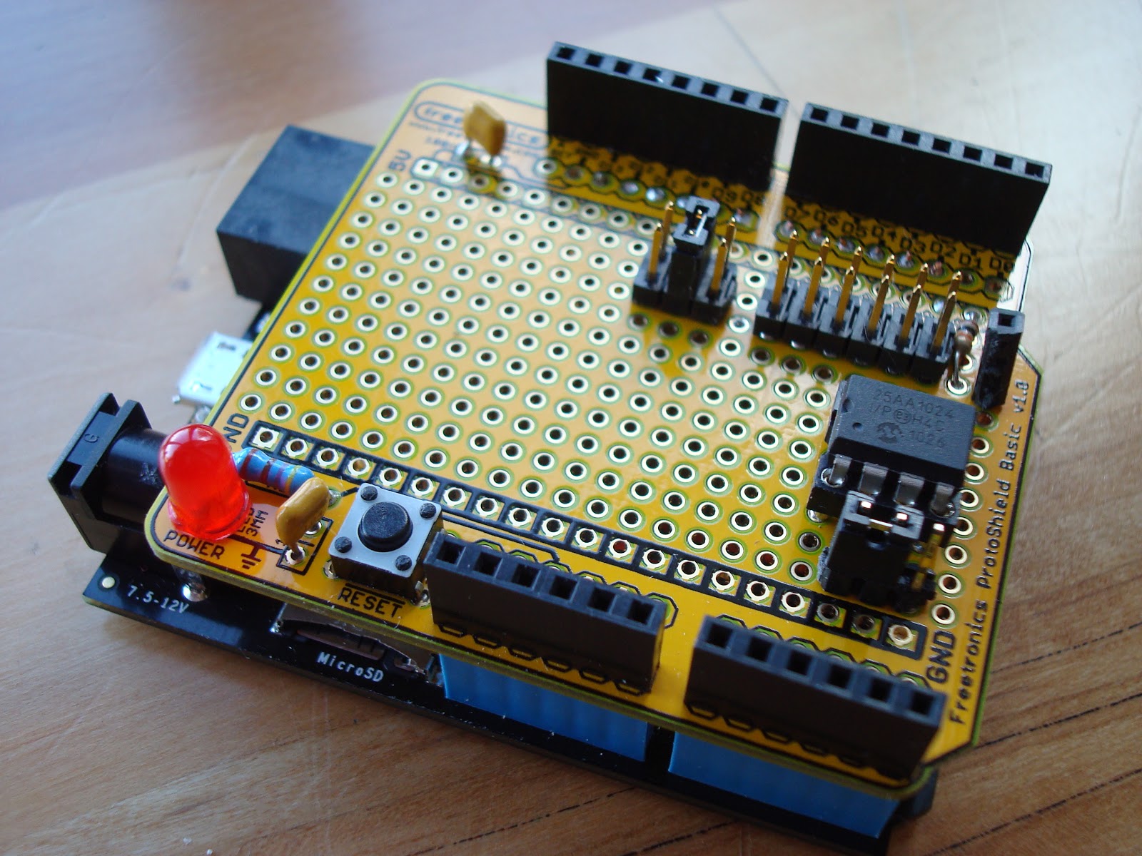
This I2C EEPROM shield was built to study I2C communications.  This two-wire bus involving bidirectional clock and data lines was invented by Philips (now NXP) to support a single master and multiple slaves.  A concise explanation and pseudo code is available on Wikipedia.   The shield is composed of a Microchip 24FC1025 which is a 1024 megabit (128 kilobyte) EEPROM, and supporting circuitry of jumpers, sockets, and resistors.  The jumpers provide options for the implementation to support a variety of platforms. 
 
Note: there is a strong advantage to using the I2C 24FC1025 over its SPI cousin the 25AA1024 that I highlighted in another EEPROM Shield article.  The I2C version has a simple API: write the address, then read/write bytes.  The SPI version has a complex API including erasing the whole chip, erasing a page, writing a page of memory, etc.  While the SPI device adheres to some JEDEC standards allowing for interoperability and has faster protocol speeds (20MHz) than the slower I2C device (100 kHZ, 400 kHZ, or 1MHz), using an I2C EEPROM is much faster to develop for time to market when engineering from scratch.
 
 
The form factor of the EEPROM shield supports the original Arduino such as the Duemilanove.  This also makes it compatible with a variety of other Arduino boards, and boards that are compatible with the Arduino shield form factor.  I have access to quite a few boards that are either directly compatible with this shield, or easily adapted.  Testing these boards with the EEPROM is summarized in the following table:
 

Board Type VCC Pullups SDA/SCL Solution Notes
Arduino Duemilanove arduino 5V internal A4/A5Wire.h  
Arduino Leonardo arduino 5V external D2/D3 Wire.h  
chipKIT Max32 arduino 3.3V external D20/D21 Wire.h 1
chipKIT Uno32 arduino 3.3V external A4/A5 Wire.h 2
Netduino Mini netmf 3.3V on board 9/10I2CDevice 3
Netduino Plus netmf 3.3V external A4/A5 I2CDevice  
Netduino Plus 2 netmf 3.3V external SDA/SCL I2CDevice 4
Panda II netmf 3.3V on board D2/D3I2CDevice  
FEZ Cerbuino Bee netmf 3.3V external D2/D3 SoftwareI2CBus 5, 6
Netduino Go Shield Base (Standalone) netmf 3.3V internal A4/A5 SoftwareI2C 7
 
Notes:
1. jumpered D20/D1 pins to D2/D3
2. JP6/JP8 jumpered to RG3/RG2
3. custom board used to adapt the Mini to Arduino form factor
4. jumpered SDA/SCL pins to D2/D3 or A4/A5
5. hardware I2C pins on Cerbuino not available to shields so using software method
6. WARNING: RESET/A1/A4 are not 5V tolerant on the Cerbuino.  I could have damaged the Cerbuino if I had used different SDA/SCL jumper settings on the EEPROM shield.
7. waiting on a fix from Secret Labs so can use I2CDevice
 
I was able to successfully access the EEPROM using all of these platforms.  The Arduino and chipKIT boards use Arduino and Arduino compatible IDEs.  The .NET Micro Framework (netmf) boards used either the included support for the I2C hardware lines, or in a couple cases had to use either included or added software drivers.  The upside of the software drivers is that the wiring is more flexible and can use CPU internal pullups, but the downside in this case is the software drivers are slower than hardware drivers.  It is recommended to use the hardware drivers if you can, but there are also software drivers available that work for all these platforms (Arduino and netmf).
 
The circuit was designed on the fly to quickly get up and running with I2C.  There are a few changes I would make to improve this circuit.
  1. Remove the 3.3V pullup options.  These were not needed.
  2. Add jumper for switching the entire circuit between 3.3V and 5V.  The EEPROM can run at lower voltages, and this would allow the shield to be compatible with non-5V tolerant platforms like the Arduino Due.
  3.  
Schematic

Sunday, March 18, 2012

EEPROM Shield

This shield was created to help learn SPI (Serial Peripheral Interface).  The hardware consists of an empty prototype shield for Arduino with a Microchip 25AA1024 EEPROM, jumpers, sockets, LED, switch, and discrete components.

This shield allows an microcontroller to store and retrieve up to 128K bytes of data using SPI at up to 20MHz speed.
The target platform was Microsoft .NET Micro Framework 4.1 as shown mounted on the Netduino Plus, and also demonstrated to work on the FEZ Panda IISource code for the project is posted at github in the form of a class library DLL and test application.  Note this code requires Microsoft .NET Micro Framework APIs and will not work on a standard Arduino.  Many others have written libraries for this chip for Arduino and other platforms.

The large array of jumpers allows configuration of the chip select line to one of digital pins 2-10.  The hold pin is pulled high and socketed to allow for future use, but is not wired to any of the microcontroller's pins.  The WP (write protect) pin is jumpered to allow it to be pulled high (disabled) or pulled low (enabled).  The circuit for the LED and reset switch was already present on the prototype shield.

A possible revision to this circuit would be to add a jumper for choosing 3.3V or 5V operation if it needs to be used with a board that is not 5V tolerant.  The boards I used run at 3.3V but are 5V tolerant. 

Future revisions to the source code could include supporting a wider range of EEPROMs from Microchip, SST, and other manufacturers, and/or porting the code to other platforms including mbed, chipKIT, PIC, and Arduino.


EEPROM Shield Schematic
Under belly of the shield

Tuesday, October 11, 2011

Indoor/Outdoor Thermometer Shield for Arduino

This is a dual thermometer shield for Arduino.  It has ports for two temperature sensors (LM135, 235 or 335).   One sensor is local, and another can have an extended length of three conductor wire and encased in shrinkwrap tubing for weatherproofing.  The shield alternately displays the state of each of the temperature sensors in Fahrenheit. 

The temperature sensor portion of the circuit is tiny, less than a quarter square inch.  The majority of the circuit area is for the seven segment LED drivers.  The LED circuit includes 74HC4511 (one 7-segment led driver), 74HC138 (demultiplexer for led selection), and two 74HC04 chips (logic inverters).  Only one LED segment is lit at any one time, using interlacing it appears that all three are lit at once.  Using the 7-segment driver, only the digits 0-9 can be displayed, no negative numbers.

Voltage regulation is very important for this circuit, as a change in voltage will result in a change of reading.  Potentiometers are included for calibrating the sensors.

Headers are included for SPI and 5V power, to support a custom Ethernet adapter and custom SD card adapter.  Using pass-through connectors for supporting a shield on top of this one was not a priority.  A jumper is provided for running the circuit at 3.3V, but 5V operation is preferred for LED brightness; and due to the 74HC chips, the logic is compatible with any 3.3V Arduino that can source 5V power.  This shield was built on a ProtoShield and has been successfully tested with the 5V Diavolino (Arduino Duemilanove clone), 3.3V chipKIT Max32, and 3.3V GHI Electronic's Panda II.


Shield working with PIC32 based Max32
Now logging to SD card with Panda II board

Friday, July 29, 2011

WIZnet WIZ811MJ SPI ethernet module

WIZnet manufactures chips and modules making it easy to integrate ethernet into an embedded circuit design.  This WIZ811MJ model is based on their W5100 chip which has an embedded ethernet stack and is accessible by SPI and parallel microprocessor bus interfaces. 

The base module is somewhat daunting with 40 pins. The module I built is the sockets and discrete electronics to breakout only the eight (8) lines necessary for the SPI interface.

I designed this module in development of a project using GHI Electronic's Panda II.  GHI includes drivers for this WIZnet part.  Note GHI's Rhino accepts WIZnet's module directly.

From left to right the pins are GND, SCLK, MISO, MOSI, CS, RESET, INT, and 3V3.
The primary advantages of using the WIZnet part is less code and RAM size necessary to maintain an ethernet stack, its low cost, and being accessible via methods that a microprocessor can easily handle.