Monday, September 19, 2011

Car Alarm

This summer an opportunistic small time thief has been roaming our neighborhood stealing ipods from unlocked cars.  To discourage them messing with our vehicles, I built this circuit and installed it in my wife's car.  We use a rechargable 9V battery and recharge/replace it about every two days.  This project was fast to develop and satisfying to see in action.


Build #2 with battery inside

Wednesday, September 14, 2011

LED Bar

In bread boarding a micro controller circuit, one of the most popular components is an LED.  Light up an LED to indicate power connected, turn it on or off based on a mode change, or flash an LED to indicate the CPU is working.  Because LEDs are typically rated for less current than a CPU or power supply can provide, they require a current limiting resistor to keep them from burning out. 


One of my tasks in learning about new processors, is to see if I can configure every line as an output port, and if I can run the CPU at its maximum speed.  I set up an integer counter in my code, and bit shift the value into all the output lines I care about.  Using this LED bar, I can insert it into the breadboard next to the CPU pins, flip the switches off to lines I don't want to bother or mess with (like crystals, voltage regulator configuration, USB lines, etc.) and if everything works out right, watch the lights blink on and off in binary code.

The LED bar has nine LEDs in a row encased in green plastic, with 18 pins (upper pins are the cathode and the lower pins are the anode).  Nine current limiting resistors connect the cathodes to ground through eight switches.  The rightmost LED is used to indicate power and bypasses the switches; the jumper in the upper right is the ground (top) and power (bottom) connections.  These components are placed on a mini circuit board with pins so it can sit upright on a breadboard.


Saturday, September 10, 2011

microSD Arduino adapter

Arduinos are meant to be attached to peripherals.  Here is an adapter from a 5V Arduino to a 3.3V microSD card.  To bridge the gap from circuit board to SD card, a socket is used to connect a microSD breakout board (BOB).  Resistor voltage dividers bridges the gap between the voltage differences for outputs.  A low dropout voltage regulator supplies 3.3V power for the SD card.  Inputs from the SD card are within spec for the Arduino, so they did not have to change.

This adapter is a vertical shield.  It has a socket so the pins are accessible if the attachments are compatible.  It only connects to the AREF to D8 eight position socket, which does not have power, so it requires a jumper from 5V(VCC) to one of the slots on its dual socket, so as to replace the 5V socket with another one.  It also has a 1 port card detect (CD) socket, which can be jumpered to another available pin on the Arduino.

It is modeled to support the SD CardInfo example included in the Arudino IDE.  Chip select (CS) is connected to D8 with a jumper, it can be moved to D9 or D10.  It can be used simultaneously with the Ethernet non-shield.


5V Arduino SD Adapter Schematic

Tuesday, September 6, 2011

My own first PIC32 Development Board

Here is a USB PIC32 development board that is in progress.  I bought a bare 64-pin PIC32MX795F512H which is the highest end Microchip 32-bit CPU, except for having 36 fewer pins pins than its close sibling.  This CPU has 512K Flash, 128K RAM, and runs at 80MHz.

It was soldered to a breakout board that is connected by dual row 0.1" 16-pin headers so it can be mounted in sockets on a standard solder breadboard.  It has three symmetrical 8 pin headers which expose shared SPI/UART (total of 6 RX/TX pairs), and power lines.  Jumpers choose between USB host and USB device functionality.
The first test of this board was as a four port RS-485 monitor.  I was able to enhance the monitor's protocol to support four sources, then enhanced it as a bidirectional adapter.  The code is built on Microchip's USB device CDC sample and shared among various PIC targets, so the code is also supported on other various 8-bit and 16-bit PICs too.

A planned test is to breakout the RMII/MII lines to an Ethernet PHY and test the Ethernet capability of this CPU.  I purchased a QFN 36-pin SMSC LAN8700 PHY but unfortunately I cannot find a compatible breakout board for it.  Nine pin sides seem to be an odd number, and the breakouts I have tried are built for even numbered pins per side making this one just a bit too small to work with the traces.  My next plan is to try a QFN 24-pin SMSC LAN8720 PHY.

Another plan is to get it to work with the chipKIT Arduino-Compatible Prototyping Platform so it can be programmed in C++.

Monday, September 5, 2011

Arduino Ethernet Shield without the Shield

This project adds Ethernet to an Arduino.

I had already purchased the WIZ811MJ module, and crafted the W5100 SPI module which essentially has the components of a basic Arduino Ethernet shield without SD support. After recently aquiring an Arduino Duemilanove clone, the Diavolino, I used jumper wires to connect the two, but it was too messy. Using solid wire soldered to female headers, and one stray connector wire, I resulted in a cleaner solution. The ethernet module runs on 3.3V but this Arduino runs on 5V, so a voltage regulator circuit was necessary, and ended up soldering it right to one of the headers along with support capacitors (a cleaner look would involve shrink wrap tubing). The W5100 tolerates 5V inputs and the 3.3V outputs are accepted correctly by the Arduino, so no signal voltage translations were necessary. I successfully tested this adapter cable with the Arduino example Ethernet telnet client. 

The entire adapter
Angled perspective

View with Voltage Regulator

Saturday, September 3, 2011

Serial Text LCD

Serial Text LCD module
This project connects a Text LCD display to a microcontroller or PC via a single serial transmission line (plus power).
One of the challenges of integrating a text LCD display is the number of pins to connect. A display module typically has 16 lines, with 11 for data and control. That's a lot of lines for a microprocessor to handle. One way to handle it is to get an I/O expander (I2C or SPI), another way is to use a serial protocol such as a UART. The advantage of have a UART compatible text LCD display module is that it can be controlled with just a single TX line. The downside is using up one of (or your only) microcontroller's UART transmission line, unless you can use software UARTs.
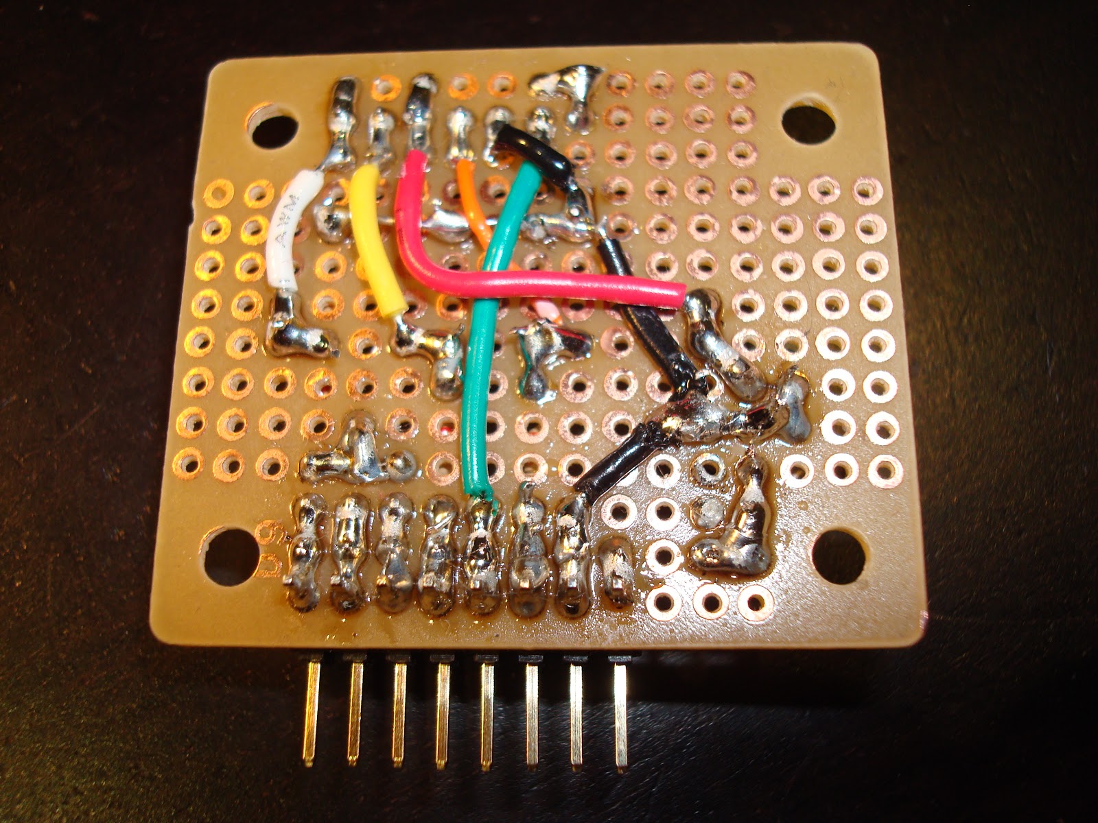
backside
Prototype with serial connections

My requirements included performing a very simple firmware implementation.  I didn't want to spend a lot of effort creating the module.  And I wanted to learn the communications with the LCD module, so limiting to just a text interface was not desired.  I ended up implementing a 6-bit raw protocol, and writing a .NET program to talk to the LCD using 4-bit mode.  I already had some firmware for my 485 monitor that I quickly adapted for use with the LCD.  Bytes are received serially on the RX line, then output to the PORTB, of which 6-bits are wired to the LCD.  After echoing the raw hex back on the TX line (for diagnostics, not necessary for operation), the data byte is strobed with bit 5 cleared to finalize communication with the LCD.  I ended up expanding on the .NET program to have a form where what is typed on the screen is efficiently updated to the LCD screen.

I want to interface with 3.3V microcontrollers, and I want the cost to be low, so I used an available PIC18F26K22 I had received as a sample from Microchip, with the circuit using 5V from USB stepped down to 3.3V with a voltage regulator for the CPU.  The LCD runs at 5V, accepting 3V logic from the CPU.  The latest version of the circuit has an added jumper to select whether the PIC runs at 3.3V or 5V, which in turn determines the I/O voltage levels of the module.  The five port socket includes 5V, 3.3V (output), Ground, TX (output), and RX.  Minimally only 5V, Ground, and TX need to be connected.  This PIC is currently configured to run at its top speed of 64MHz! (This may be overkill for just driving an LCD.)  The LED in the circuit is a heartbeat to show that the PIC is running.

.NET program and hex diagnostics 
Schematic


I plan to immediately use this module with other PIC, Arduino, and Netduino projects.  Writing the .NET program allowed me to more easily learn the LCD protocol than debugging the firmware.  I may expand the firmware to move more of the LCD protocol into the PIC18 firmware, or at least have that option.  Other possibilities are to implement I2C and/or SPI interfaces.

Update: In addition to Windows, I have had success using this module with the mbed, LPCXpresso 1769, chipKIT Max, and Arduino.