Showing posts with label SD. Show all posts

Tuesday, October 11, 2011

Indoor/Outdoor Thermometer Shield for Arduino

This is a dual thermometer shield for Arduino.  It has ports for two temperature sensors (LM135, 235 or 335).   One sensor is local, and another can have an extended length of three conductor wire and encased in shrinkwrap tubing for weatherproofing.  The shield alternately displays the state of each of the temperature sensors in Fahrenheit. 

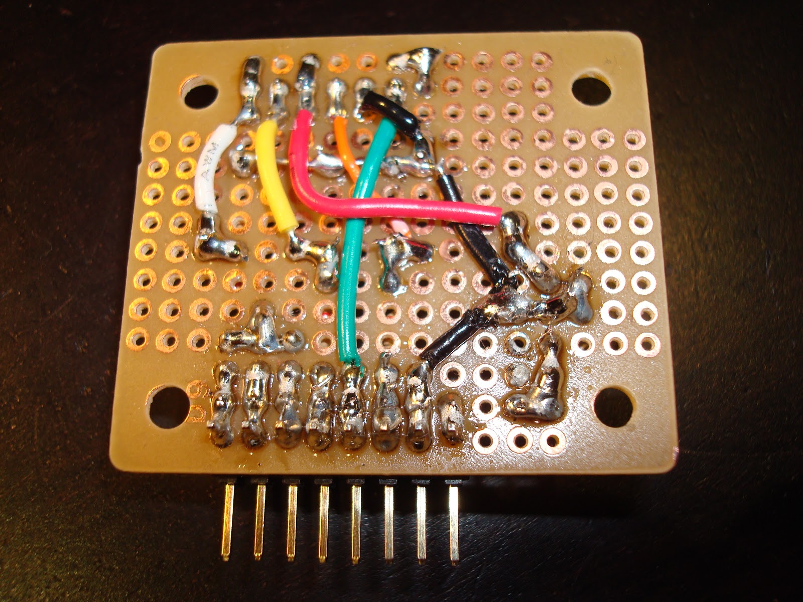
The temperature sensor portion of the circuit is tiny, less than a quarter square inch.  The majority of the circuit area is for the seven segment LED drivers.  The LED circuit includes 74HC4511 (one 7-segment led driver), 74HC138 (demultiplexer for led selection), and two 74HC04 chips (logic inverters).  Only one LED segment is lit at any one time, using interlacing it appears that all three are lit at once.  Using the 7-segment driver, only the digits 0-9 can be displayed, no negative numbers.

Voltage regulation is very important for this circuit, as a change in voltage will result in a change of reading.  Potentiometers are included for calibrating the sensors.

Headers are included for SPI and 5V power, to support a custom Ethernet adapter and custom SD card adapter.  Using pass-through connectors for supporting a shield on top of this one was not a priority.  A jumper is provided for running the circuit at 3.3V, but 5V operation is preferred for LED brightness; and due to the 74HC chips, the logic is compatible with any 3.3V Arduino that can source 5V power.  This shield was built on a ProtoShield and has been successfully tested with the 5V Diavolino (Arduino Duemilanove clone), 3.3V chipKIT Max32, and 3.3V GHI Electronic's Panda II.


Shield working with PIC32 based Max32
Now logging to SD card with Panda II board

Saturday, September 10, 2011

microSD Arduino adapter

Arduinos are meant to be attached to peripherals.  Here is an adapter from a 5V Arduino to a 3.3V microSD card.  To bridge the gap from circuit board to SD card, a socket is used to connect a microSD breakout board (BOB).  Resistor voltage dividers bridges the gap between the voltage differences for outputs.  A low dropout voltage regulator supplies 3.3V power for the SD card.  Inputs from the SD card are within spec for the Arduino, so they did not have to change.

This adapter is a vertical shield.  It has a socket so the pins are accessible if the attachments are compatible.  It only connects to the AREF to D8 eight position socket, which does not have power, so it requires a jumper from 5V(VCC) to one of the slots on its dual socket, so as to replace the 5V socket with another one.  It also has a 1 port card detect (CD) socket, which can be jumpered to another available pin on the Arduino.

It is modeled to support the SD CardInfo example included in the Arudino IDE.  Chip select (CS) is connected to D8 with a jumper, it can be moved to D9 or D10.  It can be used simultaneously with the Ethernet non-shield.


5V Arduino SD Adapter Schematic

Monday, August 8, 2011

mbed Text LCD development board


This is my take on an mbed development board to support different LCD sizes.


The three sizes shown here are 20x4, 16x2, and 8x2.  Some LCD screens have a single row of 16 pins.  Others have two columns of seven (or eight) pins.  I developed this board to not hard-wire any connections except those dedicated on the mbed itself.  The LCD screen can be wired up in 4-bit (shown) or 8-bit mode using any available I/O lines.  Additional sockets are provided for USB host, USB device, Ethernet MagJack, and microSD.  Four switches with sockets are also provided.


eBible with power from Motorola


As most everything was socketed and not hard-wired, there's a lot of solder bridges connecting the sockets.  14 or 16 of the LCD socket connections are wired together in a mass of wire under the board.  This allows using jumper wires for just the top 16 wire socket, and plugging in any of the three LCDs that I have.  One of the LCDs was modified to grab power from the 2x7 socket.  Another has an additional two leads that are socketed.  The reason for the two different 2x7 sockets was that the functions of pins 1/2 were reversed on the 16x2 LCD display.  Alternatively, I could have used a switch or relied on changing the jumper wires.

The microSD has 7 connections, so just provided a 7x2 socket, and this requires jumpering the lines to the mbed.  I can then choose which SPI connections to make, and what line to be the chip select and/or card detect.  I attach a microSD breakout board from SparkFun.

The Ethernet MagJack is hard wired except for the LEDs.  A specific breakout board from SparkFun is required.

A USB device jack is socketed to support a mini USB device breakout board.  Alternatively a USB-A cable can be connected.

Power (3.3V) and ground buses are included, hard wired to the mbed.