Showing posts with label mbed. Show all posts

Sunday, April 12, 2020

Commodore 64 for STM32F429 Discovery board

So here is a Commodore 64 emulator I built for STM32F429 Discovery board:


Yeah, the LCD is tiny at 2.4", and the emulation runs about 15% slower than an NTSC C64.  But it's running on a small embedded board that's available for under $30 US (DigiKey, Mouser, ...) including mounted LCD display and USB OTG jack.  Just add keyboard, OTG USB adapter, and power supply.

This is a port of my portable C64/6502 emulator for terminal console, which was a port of my Commodore/6502 emulator for Windows Console.   But this time, I dropped the console part, and went for real video (LCD) and USB keyboard support.   Hello PETSCII!

Keyboard mapping (showing my Dell keyboard):
   STOP(ESC) F1 F2 F3 F4 F5 F6 F7 F8            Restore(PrtScr/SysRq) Run/Stop(Pause/Break)
             1! 2@ 3# 4$ 5% 6^ 7& 8* 9( 0) -_ += Del/Ins(Back)    Ins Hme/Clr     / * -
   Ctrl(Tab) Q  W  E  R  T  Y  U  I  O  P  [  ]  £ (\)            Del           7 8 9 +
             A  S  D  F  G  H  J  K  L  ;: '" Return(ENTER)                     4 5 6
   LShift    Z  X  C  V  B  N  M  ,< .> /?  RShift                     Up       1 2 3
   C=(Ctrl)           SPACEBAR              C=(Ctrl)              Lft Down Rt   0 .   Enter

Features:
  • 320x200 text screen on graphics LCD, with top/bottom border.
  • USB Keyboard (e.g. PC-103) support (symbolic, not positional)
    • Tab maps to C64 Ctrl key
    • Ctlr maps to C64 Commodore key
    • Esc key maps to C64 RUN/STOP key
    • PrtScr/SysRq maps to C64 RESTORE key (supports STOP+RESTORE)
    • PgUp also maps to C64 RESTORE key
  • Full 6502 emulation.  Go ahead, run some machine language on it.
  • Commodore character set
  • Text video at $0400 (address 1024)
  • Text color at $D800 (address 55296)
  • Keyboard scan by writing to $DC00, reading from $DC01
  • Full 64K RAM.  Update 2020-04-14: RAM/ROM/IO/Charset banking is implemented!  And 1K color nybbles
  • 1/60 second IRQ.  So we've got the software clock: TI, TI$
  • Upper/lower case switch ($D018), and reverse characters.
  • Border color ($D020) and background color ($D021).
Limitations:
  • Approximately 85% cpu speed of a real C64
  • No NMI.  No Restore key.  Update 2020-04-15: implemented, see keyboard above.
  • No other device support.  No tape, no disk, no serial, no cartridges, no joysticks, no printer.
  • VIC-II support is limited to getting system booted.
    • No full register support.
    • Text address can't be moved.
    • No graphics support.
    • No programmable characters.
    • No raster interrupts.
    • No sprites.
    • No left/right side border displayed.  Ran out of pixels.
  • No CIA1/CIA2 (except for keyboard data ports, but no data direction registers)
  • No SID.
  • In progress.  There are bugs lurking (for example, the IRQ and USB keyboard stops working exactly at 35 minutes, 38 seconds from start, maybe a resource leak in third party libraries, so we'll call that time limited I guess)
  • Keyboard support may need tweaks for more complete PETSCII key support
  • No CAPS LOCK or SHIFT LOCK supported
  • Doesn't utilize full capabilities of the STM32F429 MCU and discovery board components including 2.0MB of Flash (uses 110KB), 256KB of RAM (uses 83KB), 8MB SDRAM, motion sensor, user leds, user button, or other expansion capabilities.  Opportunity awaits!
Links:
Credit:  

Thursday, September 26, 2013

mbedR3uino: mbed adapter for Arduino shields

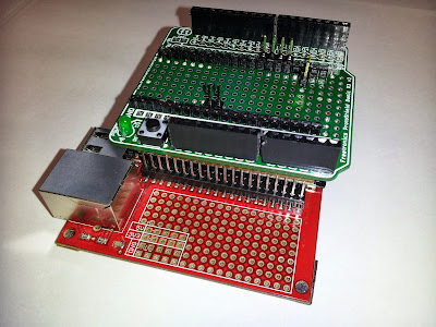
The mbedR3uino is a vertical shield adapter for the mbed prototyping platform.  It provides compatibility with standard Arduino shields including the pins added to Arduino Uno R3 to make shields more independent between main boards.

This is the project I wanted three years ago.  Finally the need, inspiration, materials, and dependent projects converged.  The ability to easily add pluggable hardware to the mbed had been demonstrated when I created the In-between Shield for mbed which plugged into the mbed workshop board adding flash memory to the mbed which plugged into the shield. 

 
I have developed a number of prototype shields for Arduino using a ProtoShield that have been compatible with my various Arduinos, Netduinos, and other development boards providing plug compatibility with Arduino shields.  With the addition of the new R3 pins: SCL, SDA, IOREF some more platform independence has occurred allowing the shield (or at least its I/O) to run at the same voltage as the target platform, and a standardization of the location of the I2C pins.  The SPI pins which were originally reserved for ICSP or initial programming of the Arduino also became a standard.  I opted to skip the SPI/ICSP pin compatibility and stick with the Uno SPI pin layout for simplicity; a future version should include the SPI/ICSP pins in their expected location.  An R3 version of the ProtoShield was found here and I had seeedstudio build the PCBs.

The mbedR3uino is named because mbeduino was already taken.  Inserting the R3 in the name gives it some uniqueness while expressing its meaning.  The adapter consists of two pluggable pieces.  The first plugs into the workshop board above the mbed providing a footprint identical to the mbed.  Components were added to the ProtoShield to plug it into the first piece, and wire the connections to the Arduino R3 headers.  The result is that Arduino shields can be connected to the mbed.


Standard height 0.45" header pins were used to connect the ProtoShield to the above mbed adapter.  The above mbed adapter used taller 0.7" header pins so the PCB barely clears the height of the mbed, only touching the mini USB socket.  Since my prototyping boards have solder terminals only on one side, and to keep them clean looking I try to solder only on the bottom, hidden from view, I used needle nose pliers to push the pins so the plastic is flush with the top of the pins, and then carefully solder the pins from the bottom of the board not getting them too hot or the pin could waver out of place.  Once all the pins are soldered into place they hold very securely.

Note that the mbed workshop board or equivalent is required.  It already provides SD, Ethernet, and USB connectivity.  I have a revA board which pin 9 is held high to 3.3V (intended for SD card detect?), so to allow it to be used for the UART, I cut the trace on the workshop board.  An alternative to using the workshop board would be to have dual row headers and connect the columns for all pins 1-40, as done in my mbed Text LCD development board.  It is relatively easy to also solder a USB B connector, and an Arduino shield can be used for an SD card.  Connecting an Ethernet jack directly to the mbed can be done using a breakout board.

All the available pins on the mbed are either connected to the Arduino headers, or a few are broken out for additional expansion: since the workshop board already uses pins 5-8, they were left as an expansion; CAN and battery lines are implemented as jumpers for expansion.  Analog pins and power pins are where they should be, one UART is wired to D0/D1 for Arduino compatibility, and one SPI is wired for original Uno compatibility (D13-D10).  One pair of I2C pins are in the new R3 location, and the same pins are also wired to the same location as done with the Leonardo: D2/D3.  The remaining D14 and PWM pins are wired to the remaining Arduino header pins.  The schematic below shows how I chose to map the pins between the boards.

Schematic - Click on image to view larger

Thursday, April 12, 2012

In-between Shield for mbed with 128Mbit Flash


In-between Flash Shield with SST25VF064C
The "In-between Shield" has been developed as a means to extend the attached peripherals of the mbed in a clean looking manner, inspired by the expandability of Arduino, but unique and true to the mbed experience.
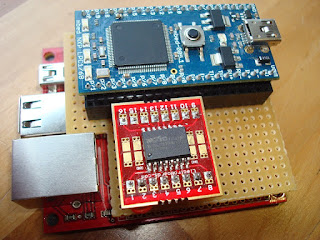
This shield is designed to fit and work with the workshop board for mbed.  This is a a breakout board for Ethernet, USB, and SD for mbed.  Instead of the mbed placed in the workshop board, the in-between shield is placed first, and the mbed sits on the shield.  It should be possible to stack additional shields depending on the height of the components on each shield.

The shield itself is composed of a solder breadboard cut to the dimensions of the workshop board, with an additional cutout to avoid the height of the Ethernet jack.  I reduced this board's dimensions further so the USB ports can be visible from above.  This visibility helps with attaching cables and devices.


workshop board
In-between shield
underside
Flash breakout boards


Above board shield in use
The first in-between shield has two 8-pin sockets to accommodate a 16-pin SOIC breakout board with a flash chip attached (SST25VF064C or MX25L12835E).  The flash breakout board can be easily changed out to attach different flash parts. Wiring beneath the shield connects the necessary pins back to the mbed.  The mbed sits in two 2x20 wire wrapping sockets.  No wire wrapping is used in this project.  The advantage to the wire wrapping sockets is the extended leads so the shield sits above the workshop board.

The dual row sockets are used to extend the purpose of the workshop board: each side of the mbed sits in one row, and another row is provided for allowing jumper wires or a single above board shield. The rows of pins are not connected with the shield, it depends on their connections in the workshop board. If the workshop board is not available, a good substitute is another solder breadboard with two 2x20 sockets (short leads), with solder bridges between the pins. 
Solder bridges


The evolution of the flash shield included an ugly do it yourself SOIC to 2x4 pins breakout board made up from two separate 50 mils pitch boards, one for each side of the SOIC chip. An additional board was made to adapt dual 2x4 sockets to a single row 8-pin breadboard friendly connector, with LED to show power. The next iteration was an above mbed board using long single row headers that can be soldered to the bottom of a solder breadboard. Last but not least, the in-between shield was created.

First prototype and breakouts
Above board shield prototype

Source code for this project is posted here. Driver for SST 64Mbit flash (8Mbyte) model 25VF064C including higher level methods for rewrite and buffered read/write to help optimize I/O. Can also work with other 25 series flash and eeprom devices, requiring minor revisions for their capabilities.

The end result of the in-between shield is a clean looking prototype of an mbed connected to a SOIC flash chip that can be further expanded.

Shield shown with MX25L12835E 128Mb Flash

Monday, August 8, 2011

mbed Text LCD development board


This is my take on an mbed development board to support different LCD sizes.


The three sizes shown here are 20x4, 16x2, and 8x2.  Some LCD screens have a single row of 16 pins.  Others have two columns of seven (or eight) pins.  I developed this board to not hard-wire any connections except those dedicated on the mbed itself.  The LCD screen can be wired up in 4-bit (shown) or 8-bit mode using any available I/O lines.  Additional sockets are provided for USB host, USB device, Ethernet MagJack, and microSD.  Four switches with sockets are also provided.


eBible with power from Motorola


As most everything was socketed and not hard-wired, there's a lot of solder bridges connecting the sockets.  14 or 16 of the LCD socket connections are wired together in a mass of wire under the board.  This allows using jumper wires for just the top 16 wire socket, and plugging in any of the three LCDs that I have.  One of the LCDs was modified to grab power from the 2x7 socket.  Another has an additional two leads that are socketed.  The reason for the two different 2x7 sockets was that the functions of pins 1/2 were reversed on the 16x2 LCD display.  Alternatively, I could have used a switch or relied on changing the jumper wires.

The microSD has 7 connections, so just provided a 7x2 socket, and this requires jumpering the lines to the mbed.  I can then choose which SPI connections to make, and what line to be the chip select and/or card detect.  I attach a microSD breakout board from SparkFun.

The Ethernet MagJack is hard wired except for the LEDs.  A specific breakout board from SparkFun is required.

A USB device jack is socketed to support a mini USB device breakout board.  Alternatively a USB-A cable can be connected.

Power (3.3V) and ground buses are included, hard wired to the mbed.

Saturday, July 23, 2011

eBible


I developed this eBible for the NXP mbed Design Challenge in February 2011. It utilizes an mbed prototying board socketed along with a small LCD text screen, buttons, SD card socket, and other custom circuitry.

Abstract, documentation, schematics, C++ source, etc. are available on the mbed.org site.