Showing posts with label shield. Show all posts

Thursday, September 26, 2013

mbedR3uino: mbed adapter for Arduino shields

The mbedR3uino is a vertical shield adapter for the mbed prototyping platform.  It provides compatibility with standard Arduino shields including the pins added to Arduino Uno R3 to make shields more independent between main boards.

This is the project I wanted three years ago.  Finally the need, inspiration, materials, and dependent projects converged.  The ability to easily add pluggable hardware to the mbed had been demonstrated when I created the In-between Shield for mbed which plugged into the mbed workshop board adding flash memory to the mbed which plugged into the shield. 

 
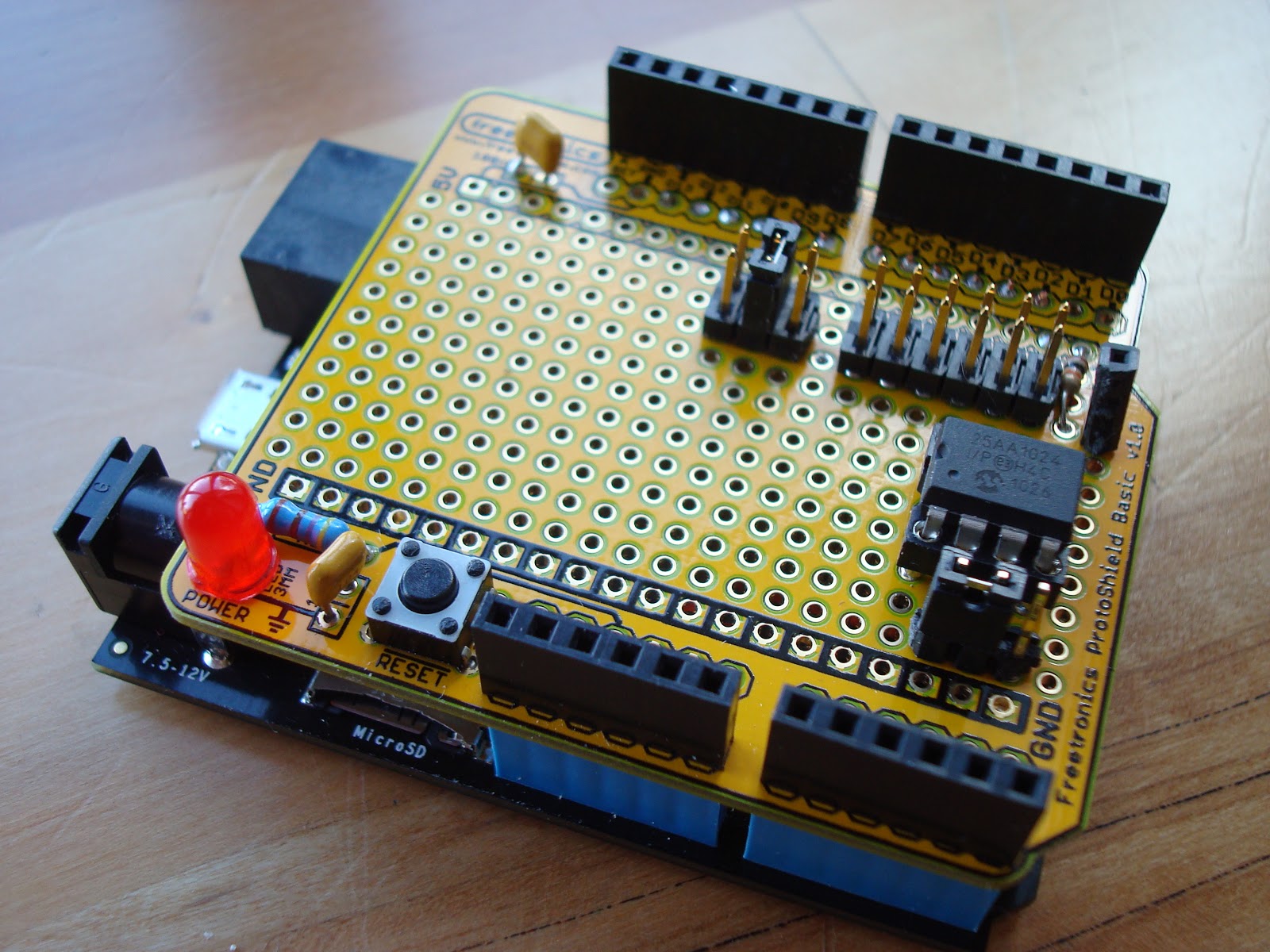
I have developed a number of prototype shields for Arduino using a ProtoShield that have been compatible with my various Arduinos, Netduinos, and other development boards providing plug compatibility with Arduino shields.  With the addition of the new R3 pins: SCL, SDA, IOREF some more platform independence has occurred allowing the shield (or at least its I/O) to run at the same voltage as the target platform, and a standardization of the location of the I2C pins.  The SPI pins which were originally reserved for ICSP or initial programming of the Arduino also became a standard.  I opted to skip the SPI/ICSP pin compatibility and stick with the Uno SPI pin layout for simplicity; a future version should include the SPI/ICSP pins in their expected location.  An R3 version of the ProtoShield was found here and I had seeedstudio build the PCBs.

The mbedR3uino is named because mbeduino was already taken.  Inserting the R3 in the name gives it some uniqueness while expressing its meaning.  The adapter consists of two pluggable pieces.  The first plugs into the workshop board above the mbed providing a footprint identical to the mbed.  Components were added to the ProtoShield to plug it into the first piece, and wire the connections to the Arduino R3 headers.  The result is that Arduino shields can be connected to the mbed.


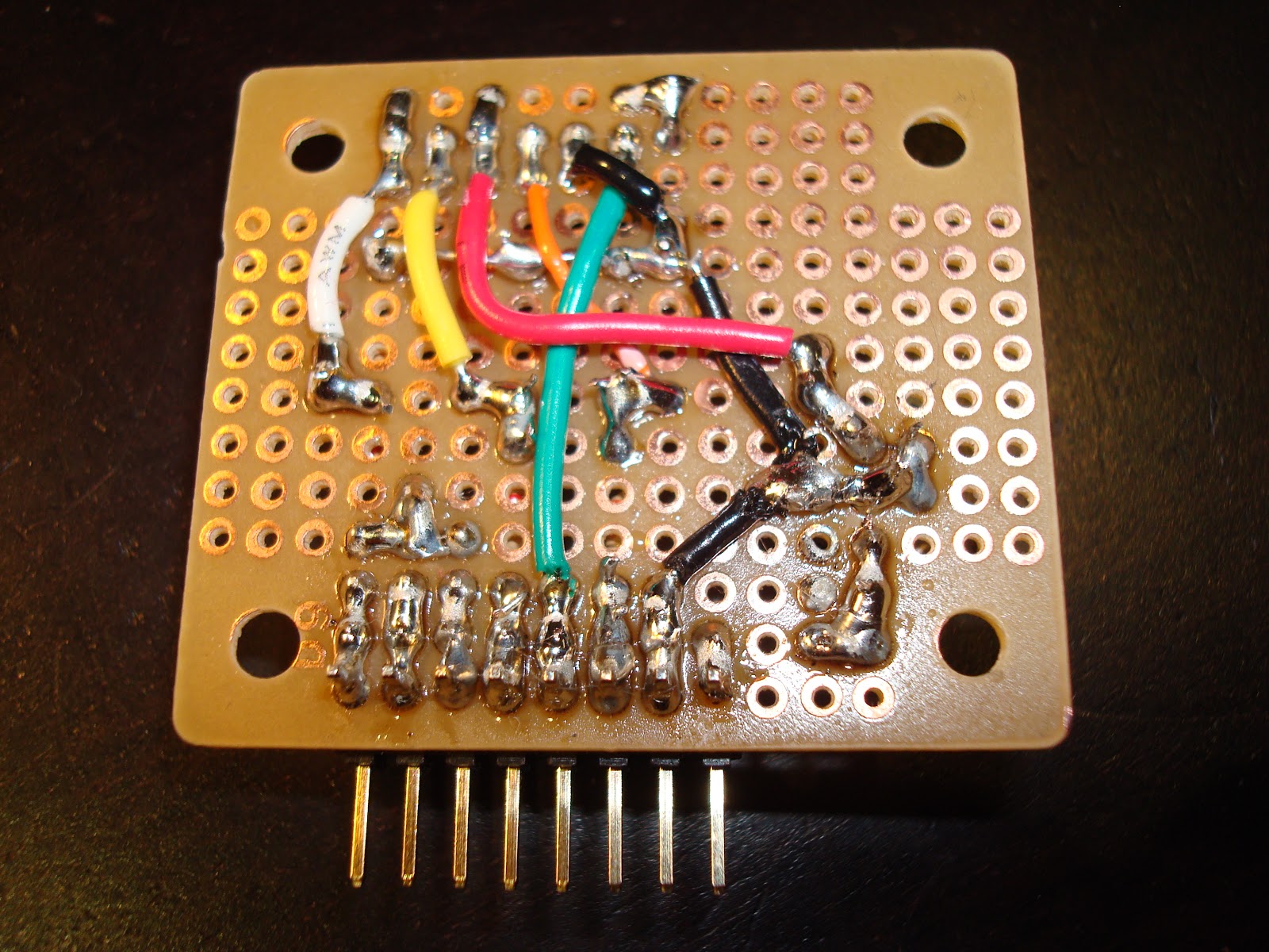
Standard height 0.45" header pins were used to connect the ProtoShield to the above mbed adapter.  The above mbed adapter used taller 0.7" header pins so the PCB barely clears the height of the mbed, only touching the mini USB socket.  Since my prototyping boards have solder terminals only on one side, and to keep them clean looking I try to solder only on the bottom, hidden from view, I used needle nose pliers to push the pins so the plastic is flush with the top of the pins, and then carefully solder the pins from the bottom of the board not getting them too hot or the pin could waver out of place.  Once all the pins are soldered into place they hold very securely.

Note that the mbed workshop board or equivalent is required.  It already provides SD, Ethernet, and USB connectivity.  I have a revA board which pin 9 is held high to 3.3V (intended for SD card detect?), so to allow it to be used for the UART, I cut the trace on the workshop board.  An alternative to using the workshop board would be to have dual row headers and connect the columns for all pins 1-40, as done in my mbed Text LCD development board.  It is relatively easy to also solder a USB B connector, and an Arduino shield can be used for an SD card.  Connecting an Ethernet jack directly to the mbed can be done using a breakout board.

All the available pins on the mbed are either connected to the Arduino headers, or a few are broken out for additional expansion: since the workshop board already uses pins 5-8, they were left as an expansion; CAN and battery lines are implemented as jumpers for expansion.  Analog pins and power pins are where they should be, one UART is wired to D0/D1 for Arduino compatibility, and one SPI is wired for original Uno compatibility (D13-D10).  One pair of I2C pins are in the new R3 location, and the same pins are also wired to the same location as done with the Leonardo: D2/D3.  The remaining D14 and PWM pins are wired to the remaining Arduino header pins.  The schematic below shows how I chose to map the pins between the boards.

Schematic - Click on image to view larger

Saturday, September 7, 2013

3V-5V Switchable I2C Real Time Clock Shield


This is a prototyped Arduino shield that is 5V and 3V switchable.  The real time clock (RTC) is a DS1307 running at 5V, with a backup battery to keep time while not plugged into another power source.  It connects with an Arduino or similar board via I2C, but using a voltage translation (level shifter) circuit using FETs (reference: Philips) to isolate the RTC chip that always runs at 5V from the Arduino CPU which can be running at either 5V or 3V.  This provides support for 3V Arduino format boards such as the Arduino Due which can be damaged if 5V is applied to its lines.  Jumpers are provided to select the voltage (red), the I2C lines used (D3/D2 or A5/A4), and whether 3.3K pull-ups are used on the microcontroller side of the circuit.  Note the RTC always has its pull-ups in place.

Note that due to USPS regulations, Lithium batteries cannot (without meeting specific conditions) be shipped via US airmail so my Digi-Key order that included the FETs and crystal was revised to eliminate the batteries.  These are available cheap in bulk from many distributors, but to save immediate costs including shipping I ended up purchasing a single one at the local drug store.  Next time I may use ground shipping for such items, but I also found a local electronics supplier that has a decent price.
 
The DS3107 chip was purchased overseas via eBay as it was available much cheaper than domestically.  Hint: look for free shipping.
Schematic


A different 3V RTC chip could also be used, such as a surface mount chip, and then the level shifting circuit (FET drain/source) needs to be reversed per the original circuit recommended by Philips Semiconductors because the low/high sides of the circuit are reversed when the RTC is running at 3V and the microcontroller is running at 5V.
For prototyping the FETs ordered are in package TO92-3.  I ordered two different FETs and ended up using the more expensive ones with a higher Vdss rating (200V).  A cheaper FET in SOT-23 packaging with a lower rating of 50V was also sourced but not tested.
Adafruit has a tutorial including an Arduino library for use with the DS1307.  I tested this library on the Arduino Leonardo and Duemillanove running at 5V.  For the 3V Due, I used simple raw I2C (Wire library) commands to talk to the DS1307.  Only SCL1/SDA1 worked for me on the Due (had to jumper these as the ProtoShield is pre-R3 and doesn't have dedicated SCL/SDA pins).


(I had meant to publish this article in February but due to some bad soldering on my part and challenges with the Due, this prototype wasn't working properly.  Took multiple re-visits to fix everything.  Now I am very glad it is working now.)

Sunday, December 2, 2012

I2C EEPROM Shield and Platforms Roundup


This I2C EEPROM shield was built to study I2C communications.  This two-wire bus involving bidirectional clock and data lines was invented by Philips (now NXP) to support a single master and multiple slaves.  A concise explanation and pseudo code is available on Wikipedia.   The shield is composed of a Microchip 24FC1025 which is a 1024 megabit (128 kilobyte) EEPROM, and supporting circuitry of jumpers, sockets, and resistors.  The jumpers provide options for the implementation to support a variety of platforms. 
 
Note: there is a strong advantage to using the I2C 24FC1025 over its SPI cousin the 25AA1024 that I highlighted in another EEPROM Shield article.  The I2C version has a simple API: write the address, then read/write bytes.  The SPI version has a complex API including erasing the whole chip, erasing a page, writing a page of memory, etc.  While the SPI device adheres to some JEDEC standards allowing for interoperability and has faster protocol speeds (20MHz) than the slower I2C device (100 kHZ, 400 kHZ, or 1MHz), using an I2C EEPROM is much faster to develop for time to market when engineering from scratch.
 
 
The form factor of the EEPROM shield supports the original Arduino such as the Duemilanove.  This also makes it compatible with a variety of other Arduino boards, and boards that are compatible with the Arduino shield form factor.  I have access to quite a few boards that are either directly compatible with this shield, or easily adapted.  Testing these boards with the EEPROM is summarized in the following table:
 

Board Type VCC Pullups SDA/SCL Solution Notes
Arduino Duemilanove arduino 5V internal A4/A5Wire.h  
Arduino Leonardo arduino 5V external D2/D3 Wire.h  
chipKIT Max32 arduino 3.3V external D20/D21 Wire.h 1
chipKIT Uno32 arduino 3.3V external A4/A5 Wire.h 2
Netduino Mini netmf 3.3V on board 9/10I2CDevice 3
Netduino Plus netmf 3.3V external A4/A5 I2CDevice  
Netduino Plus 2 netmf 3.3V external SDA/SCL I2CDevice 4
Panda II netmf 3.3V on board D2/D3I2CDevice  
FEZ Cerbuino Bee netmf 3.3V external D2/D3 SoftwareI2CBus 5, 6
Netduino Go Shield Base (Standalone) netmf 3.3V internal A4/A5 SoftwareI2C 7
 
Notes:
1. jumpered D20/D1 pins to D2/D3
2. JP6/JP8 jumpered to RG3/RG2
3. custom board used to adapt the Mini to Arduino form factor
4. jumpered SDA/SCL pins to D2/D3 or A4/A5
5. hardware I2C pins on Cerbuino not available to shields so using software method
6. WARNING: RESET/A1/A4 are not 5V tolerant on the Cerbuino.  I could have damaged the Cerbuino if I had used different SDA/SCL jumper settings on the EEPROM shield.
7. waiting on a fix from Secret Labs so can use I2CDevice
 
I was able to successfully access the EEPROM using all of these platforms.  The Arduino and chipKIT boards use Arduino and Arduino compatible IDEs.  The .NET Micro Framework (netmf) boards used either the included support for the I2C hardware lines, or in a couple cases had to use either included or added software drivers.  The upside of the software drivers is that the wiring is more flexible and can use CPU internal pullups, but the downside in this case is the software drivers are slower than hardware drivers.  It is recommended to use the hardware drivers if you can, but there are also software drivers available that work for all these platforms (Arduino and netmf).
 
The circuit was designed on the fly to quickly get up and running with I2C.  There are a few changes I would make to improve this circuit.
  1. Remove the 3.3V pullup options.  These were not needed.
  2. Add jumper for switching the entire circuit between 3.3V and 5V.  The EEPROM can run at lower voltages, and this would allow the shield to be compatible with non-5V tolerant platforms like the Arduino Due.
  3.  
Schematic

Saturday, October 13, 2012

USB RS-485 Adapter Surface Mount Boards

The surface mount PCB version of my RS-485 adapter recently arrived from overseas.  This one is cheaper and cleaner using the 20-pin PIC18F14K50, mostly surface mount parts, and fewer LEDs.  These require more patience to build than the through hole version.

I like the expansion ports on this one.  They are Arduino-esque, with power rails opposite data rails, allowing good stability of possible shield expandability.  Every data pin, including the ones used for RS-485 are drawn out to pads. 

Jumpers are provided to choose whether to connect the RS-485 read enable and drive enable lines from PORTB or PORTC.  This allows for varied resource allocation depending on the other I/O used.  If PORTC is completely free, it can be used as a full 8-bit I/O port.  Otherwise SPI can be used.
 
The first board I built out has the headers, and a Beau Interconnect (now Molex) terminal block socket with detachable screw terminals socket.  The second board built has dedicated screw terminals and no headers for a cleaner look.
 
If you look closely, you can see the green wire work done on the first board due to me stripping a pad of one of the capacitors while trying to replace an incorrect value capacitor.  And I originally built the first one with a 4MHz crystal before reading the datasheet and realizing a 12MHz or 48MHz crystal are the only ones that work for USB with this cpu.  I was able to remove the wrong crystal using two soldering irons, and then replaced it with the 12MHz crystal after another order from Digi-Key.
 
Next step is to load these with the Microchip USB HID bootloader, write up some documentation, and start selling some on eBay.


Thursday, April 12, 2012

In-between Shield for mbed with 128Mbit Flash


In-between Flash Shield with SST25VF064C
The "In-between Shield" has been developed as a means to extend the attached peripherals of the mbed in a clean looking manner, inspired by the expandability of Arduino, but unique and true to the mbed experience.
This shield is designed to fit and work with the workshop board for mbed.  This is a a breakout board for Ethernet, USB, and SD for mbed.  Instead of the mbed placed in the workshop board, the in-between shield is placed first, and the mbed sits on the shield.  It should be possible to stack additional shields depending on the height of the components on each shield.

The shield itself is composed of a solder breadboard cut to the dimensions of the workshop board, with an additional cutout to avoid the height of the Ethernet jack.  I reduced this board's dimensions further so the USB ports can be visible from above.  This visibility helps with attaching cables and devices.


workshop board
In-between shield
underside
Flash breakout boards


Above board shield in use
The first in-between shield has two 8-pin sockets to accommodate a 16-pin SOIC breakout board with a flash chip attached (SST25VF064C or MX25L12835E).  The flash breakout board can be easily changed out to attach different flash parts. Wiring beneath the shield connects the necessary pins back to the mbed.  The mbed sits in two 2x20 wire wrapping sockets.  No wire wrapping is used in this project.  The advantage to the wire wrapping sockets is the extended leads so the shield sits above the workshop board.

The dual row sockets are used to extend the purpose of the workshop board: each side of the mbed sits in one row, and another row is provided for allowing jumper wires or a single above board shield. The rows of pins are not connected with the shield, it depends on their connections in the workshop board. If the workshop board is not available, a good substitute is another solder breadboard with two 2x20 sockets (short leads), with solder bridges between the pins. 
Solder bridges


The evolution of the flash shield included an ugly do it yourself SOIC to 2x4 pins breakout board made up from two separate 50 mils pitch boards, one for each side of the SOIC chip. An additional board was made to adapt dual 2x4 sockets to a single row 8-pin breadboard friendly connector, with LED to show power. The next iteration was an above mbed board using long single row headers that can be soldered to the bottom of a solder breadboard. Last but not least, the in-between shield was created.

First prototype and breakouts
Above board shield prototype

Source code for this project is posted here. Driver for SST 64Mbit flash (8Mbyte) model 25VF064C including higher level methods for rewrite and buffered read/write to help optimize I/O. Can also work with other 25 series flash and eeprom devices, requiring minor revisions for their capabilities.

The end result of the in-between shield is a clean looking prototype of an mbed connected to a SOIC flash chip that can be further expanded.

Shield shown with MX25L12835E 128Mb Flash

Sunday, March 18, 2012

EEPROM Shield

This shield was created to help learn SPI (Serial Peripheral Interface).  The hardware consists of an empty prototype shield for Arduino with a Microchip 25AA1024 EEPROM, jumpers, sockets, LED, switch, and discrete components.

This shield allows an microcontroller to store and retrieve up to 128K bytes of data using SPI at up to 20MHz speed.
The target platform was Microsoft .NET Micro Framework 4.1 as shown mounted on the Netduino Plus, and also demonstrated to work on the FEZ Panda IISource code for the project is posted at github in the form of a class library DLL and test application.  Note this code requires Microsoft .NET Micro Framework APIs and will not work on a standard Arduino.  Many others have written libraries for this chip for Arduino and other platforms.

The large array of jumpers allows configuration of the chip select line to one of digital pins 2-10.  The hold pin is pulled high and socketed to allow for future use, but is not wired to any of the microcontroller's pins.  The WP (write protect) pin is jumpered to allow it to be pulled high (disabled) or pulled low (enabled).  The circuit for the LED and reset switch was already present on the prototype shield.

A possible revision to this circuit would be to add a jumper for choosing 3.3V or 5V operation if it needs to be used with a board that is not 5V tolerant.  The boards I used run at 3.3V but are 5V tolerant. 

Future revisions to the source code could include supporting a wider range of EEPROMs from Microchip, SST, and other manufacturers, and/or porting the code to other platforms including mbed, chipKIT, PIC, and Arduino.


EEPROM Shield Schematic
Under belly of the shield

Sunday, December 18, 2011

Individually Addressable and Dimmable Christmas Lights


This project was inspired by a Radio Shack print advertisement or similar article showing how to make a strand of Christmas lights using LEDs and an Ethernet cable connected to an Arduino controller.  I stole the idea and created the rest from scratch.


Christmas LED Shield
I found some large 1cm diameter LEDs that look like jelly beans at a local surplus electronics warehouse, and swapped out a black Ethernet cable that was in use in my house.  Having just completed assembly my Arduino Duemilanove kit, and being the middle of December, assembling Christmas lights seemed like the logical next project.  Originally I was going to place the LEDs 11 inches apart to use up the entire length of Ethernet cable, but my wife talked me into having them closer together, so after making cuts in the outer covering at 11 inches, I made additional cuts halfway between them, now every 5.5 inches. 

Curtain Rod Installation
The point of using an Arduino is addressing the individual LEDs.  As the Ethernet cable has eight wires, that could accommodate seven LEDs (seven lines of power, one common ground), so the original plan was to include seven and the Christmas Light Shield shown does support seven LEDs.  But the Arduino Duemilanove supports exactly six PWM (pulse width modulation) outputs at D11, D10, D9, D6, D5, and D3, so I settled on a six LED strand.  Each light can be individually dimmed to a resolution of 256 values (0=off, 255=bright).  This allows the lights to chase, flash, dim, and perform other light patterns.  Two inputs (in addition to reset) were added to the shield to control the nine patterns of the lights programmed into the Arduino.


The shield was built on a empty prototype PCB, with an attached RJ45 jack and corresponding breakout board.  The lines of the Ethernet jack were wired to the PWM ports using 500K resistors.  The switches were wired to inputs at D2 and D8 with 18K pull down resistors, and those circuits are wired to 5V when the switches are pushed.  The RJ45 jack turned out to be a great way to connect and disconnect the wires.

Merry Christmas!

Tuesday, October 11, 2011

Indoor/Outdoor Thermometer Shield for Arduino

This is a dual thermometer shield for Arduino.  It has ports for two temperature sensors (LM135, 235 or 335).   One sensor is local, and another can have an extended length of three conductor wire and encased in shrinkwrap tubing for weatherproofing.  The shield alternately displays the state of each of the temperature sensors in Fahrenheit. 

The temperature sensor portion of the circuit is tiny, less than a quarter square inch.  The majority of the circuit area is for the seven segment LED drivers.  The LED circuit includes 74HC4511 (one 7-segment led driver), 74HC138 (demultiplexer for led selection), and two 74HC04 chips (logic inverters).  Only one LED segment is lit at any one time, using interlacing it appears that all three are lit at once.  Using the 7-segment driver, only the digits 0-9 can be displayed, no negative numbers.

Voltage regulation is very important for this circuit, as a change in voltage will result in a change of reading.  Potentiometers are included for calibrating the sensors.

Headers are included for SPI and 5V power, to support a custom Ethernet adapter and custom SD card adapter.  Using pass-through connectors for supporting a shield on top of this one was not a priority.  A jumper is provided for running the circuit at 3.3V, but 5V operation is preferred for LED brightness; and due to the 74HC chips, the logic is compatible with any 3.3V Arduino that can source 5V power.  This shield was built on a ProtoShield and has been successfully tested with the 5V Diavolino (Arduino Duemilanove clone), 3.3V chipKIT Max32, and 3.3V GHI Electronic's Panda II.


Shield working with PIC32 based Max32
Now logging to SD card with Panda II board

Saturday, September 10, 2011

microSD Arduino adapter

Arduinos are meant to be attached to peripherals.  Here is an adapter from a 5V Arduino to a 3.3V microSD card.  To bridge the gap from circuit board to SD card, a socket is used to connect a microSD breakout board (BOB).  Resistor voltage dividers bridges the gap between the voltage differences for outputs.  A low dropout voltage regulator supplies 3.3V power for the SD card.  Inputs from the SD card are within spec for the Arduino, so they did not have to change.

This adapter is a vertical shield.  It has a socket so the pins are accessible if the attachments are compatible.  It only connects to the AREF to D8 eight position socket, which does not have power, so it requires a jumper from 5V(VCC) to one of the slots on its dual socket, so as to replace the 5V socket with another one.  It also has a 1 port card detect (CD) socket, which can be jumpered to another available pin on the Arduino.

It is modeled to support the SD CardInfo example included in the Arudino IDE.  Chip select (CS) is connected to D8 with a jumper, it can be moved to D9 or D10.  It can be used simultaneously with the Ethernet non-shield.


5V Arduino SD Adapter Schematic