Sunday, December 2, 2012

I2C EEPROM Shield and Platforms Roundup


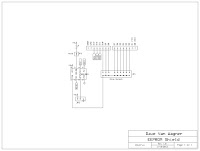
This I2C EEPROM shield was built to study I2C communications.  This two-wire bus involving bidirectional clock and data lines was invented by Philips (now NXP) to support a single master and multiple slaves.  A concise explanation and pseudo code is available on Wikipedia.   The shield is composed of a Microchip 24FC1025 which is a 1024 megabit (128 kilobyte) EEPROM, and supporting circuitry of jumpers, sockets, and resistors.  The jumpers provide options for the implementation to support a variety of platforms. 
 
Note: there is a strong advantage to using the I2C 24FC1025 over its SPI cousin the 25AA1024 that I highlighted in another EEPROM Shield article.  The I2C version has a simple API: write the address, then read/write bytes.  The SPI version has a complex API including erasing the whole chip, erasing a page, writing a page of memory, etc.  While the SPI device adheres to some JEDEC standards allowing for interoperability and has faster protocol speeds (20MHz) than the slower I2C device (100 kHZ, 400 kHZ, or 1MHz), using an I2C EEPROM is much faster to develop for time to market when engineering from scratch.
 
 
The form factor of the EEPROM shield supports the original Arduino such as the Duemilanove.  This also makes it compatible with a variety of other Arduino boards, and boards that are compatible with the Arduino shield form factor.  I have access to quite a few boards that are either directly compatible with this shield, or easily adapted.  Testing these boards with the EEPROM is summarized in the following table:
 

Board Type VCC Pullups SDA/SCL Solution Notes
Arduino Duemilanove arduino 5V internal A4/A5Wire.h  
Arduino Leonardo arduino 5V external D2/D3 Wire.h  
chipKIT Max32 arduino 3.3V external D20/D21 Wire.h 1
chipKIT Uno32 arduino 3.3V external A4/A5 Wire.h 2
Netduino Mini netmf 3.3V on board 9/10I2CDevice 3
Netduino Plus netmf 3.3V external A4/A5 I2CDevice  
Netduino Plus 2 netmf 3.3V external SDA/SCL I2CDevice 4
Panda II netmf 3.3V on board D2/D3I2CDevice  
FEZ Cerbuino Bee netmf 3.3V external D2/D3 SoftwareI2CBus 5, 6
Netduino Go Shield Base (Standalone) netmf 3.3V internal A4/A5 SoftwareI2C 7
 
Notes:
1. jumpered D20/D1 pins to D2/D3
2. JP6/JP8 jumpered to RG3/RG2
3. custom board used to adapt the Mini to Arduino form factor
4. jumpered SDA/SCL pins to D2/D3 or A4/A5
5. hardware I2C pins on Cerbuino not available to shields so using software method
6. WARNING: RESET/A1/A4 are not 5V tolerant on the Cerbuino.  I could have damaged the Cerbuino if I had used different SDA/SCL jumper settings on the EEPROM shield.
7. waiting on a fix from Secret Labs so can use I2CDevice
 
I was able to successfully access the EEPROM using all of these platforms.  The Arduino and chipKIT boards use Arduino and Arduino compatible IDEs.  The .NET Micro Framework (netmf) boards used either the included support for the I2C hardware lines, or in a couple cases had to use either included or added software drivers.  The upside of the software drivers is that the wiring is more flexible and can use CPU internal pullups, but the downside in this case is the software drivers are slower than hardware drivers.  It is recommended to use the hardware drivers if you can, but there are also software drivers available that work for all these platforms (Arduino and netmf).
 
The circuit was designed on the fly to quickly get up and running with I2C.  There are a few changes I would make to improve this circuit.
  1. Remove the 3.3V pullup options.  These were not needed.
  2. Add jumper for switching the entire circuit between 3.3V and 5V.  The EEPROM can run at lower voltages, and this would allow the shield to be compatible with non-5V tolerant platforms like the Arduino Due.
  3.  
Schematic

Saturday, October 13, 2012

USB RS-485 Adapter Surface Mount Boards

The surface mount PCB version of my RS-485 adapter recently arrived from overseas.  This one is cheaper and cleaner using the 20-pin PIC18F14K50, mostly surface mount parts, and fewer LEDs.  These require more patience to build than the through hole version.

I like the expansion ports on this one.  They are Arduino-esque, with power rails opposite data rails, allowing good stability of possible shield expandability.  Every data pin, including the ones used for RS-485 are drawn out to pads. 

Jumpers are provided to choose whether to connect the RS-485 read enable and drive enable lines from PORTB or PORTC.  This allows for varied resource allocation depending on the other I/O used.  If PORTC is completely free, it can be used as a full 8-bit I/O port.  Otherwise SPI can be used.
 
The first board I built out has the headers, and a Beau Interconnect (now Molex) terminal block socket with detachable screw terminals socket.  The second board built has dedicated screw terminals and no headers for a cleaner look.
 
If you look closely, you can see the green wire work done on the first board due to me stripping a pad of one of the capacitors while trying to replace an incorrect value capacitor.  And I originally built the first one with a 4MHz crystal before reading the datasheet and realizing a 12MHz or 48MHz crystal are the only ones that work for USB with this cpu.  I was able to remove the wrong crystal using two soldering irons, and then replaced it with the 12MHz crystal after another order from Digi-Key.
 
Next step is to load these with the Microchip USB HID bootloader, write up some documentation, and start selling some on eBay.


Saturday, September 29, 2012

PIC18F2XK50 brings $3 savings

These RS-485 Adapters were originally designed using PIC18F2455 (24k flash) and PIC18F2550 (32k flash) in mind, but with the recent introduction of the PIC18F24K50 (16k flash) and PIC18F25K50 (32k flash) some serious cost savings will be achieved. 

These new CPUs are pin compatible with the existing chips, almost $2 (US) cheaper, and have internal oscillators factory tuned to be accurate enough for USB full speed operation.  This eliminates the need for an external crystal circuit including two associated capacitors bringing more than $1 (US) cost savings.

The Microchip Libraries of Applications v2012-08-22 (USB stack), MPLAB IDE v8.87, and MPLAB C compiler for PIC18 MCUs v3.43 support these new chips.  I was able to successfully port my existing code using the new stack, and compile and program the chips using MPLAB.

Thanks to Dangerous Prototypes for bringing the news of these new MCUs to my attention.  And to Microchip for providing samples so quickly.  Some stock of these 5V SPDIP chips is currently available directly from Microchip and more supply will be available in the coming months.

Friday, September 21, 2012

USB RS-485 Adapter Through Hole PCBs

Here is my first PCB design that has gone to production. I redid the schematics of my original design now implemented in Eagle and also did a two layer PCB layout. I used Seeed's PCB service to produce the PCBs, ordered parts from Digi-Key and assembled them by hand. There were two mistakes with the board. Somehow I didn't connect VCC from USB, and inadvertently connected VCC to VUSB. Three cuts and three jumpers later and the boards work fine.

Thursday, April 12, 2012

In-between Shield for mbed with 128Mbit Flash


In-between Flash Shield with SST25VF064C
The "In-between Shield" has been developed as a means to extend the attached peripherals of the mbed in a clean looking manner, inspired by the expandability of Arduino, but unique and true to the mbed experience.
This shield is designed to fit and work with the workshop board for mbed.  This is a a breakout board for Ethernet, USB, and SD for mbed.  Instead of the mbed placed in the workshop board, the in-between shield is placed first, and the mbed sits on the shield.  It should be possible to stack additional shields depending on the height of the components on each shield.

The shield itself is composed of a solder breadboard cut to the dimensions of the workshop board, with an additional cutout to avoid the height of the Ethernet jack.  I reduced this board's dimensions further so the USB ports can be visible from above.  This visibility helps with attaching cables and devices.


workshop board
In-between shield
underside
Flash breakout boards


Above board shield in use
The first in-between shield has two 8-pin sockets to accommodate a 16-pin SOIC breakout board with a flash chip attached (SST25VF064C or MX25L12835E).  The flash breakout board can be easily changed out to attach different flash parts. Wiring beneath the shield connects the necessary pins back to the mbed.  The mbed sits in two 2x20 wire wrapping sockets.  No wire wrapping is used in this project.  The advantage to the wire wrapping sockets is the extended leads so the shield sits above the workshop board.

The dual row sockets are used to extend the purpose of the workshop board: each side of the mbed sits in one row, and another row is provided for allowing jumper wires or a single above board shield. The rows of pins are not connected with the shield, it depends on their connections in the workshop board. If the workshop board is not available, a good substitute is another solder breadboard with two 2x20 sockets (short leads), with solder bridges between the pins. 
Solder bridges


The evolution of the flash shield included an ugly do it yourself SOIC to 2x4 pins breakout board made up from two separate 50 mils pitch boards, one for each side of the SOIC chip. An additional board was made to adapt dual 2x4 sockets to a single row 8-pin breadboard friendly connector, with LED to show power. The next iteration was an above mbed board using long single row headers that can be soldered to the bottom of a solder breadboard. Last but not least, the in-between shield was created.

First prototype and breakouts
Above board shield prototype

Source code for this project is posted here. Driver for SST 64Mbit flash (8Mbyte) model 25VF064C including higher level methods for rewrite and buffered read/write to help optimize I/O. Can also work with other 25 series flash and eeprom devices, requiring minor revisions for their capabilities.

The end result of the in-between shield is a clean looking prototype of an mbed connected to a SOIC flash chip that can be further expanded.

Shield shown with MX25L12835E 128Mb Flash

Saturday, March 24, 2012

3V to 5V and 5V to 3V logic converters


Here is an adapter for converting up to 4 lines of 5V logic to 3V logic and vice versa.  Using two Texas Instruments SN74AHC125N logic buffers, one running at a 5V and one running at 3V, we have bidirectional converters useful for interfacing circuits running at different voltages.

There are three jumpers.  The top jumper has 5V, ground, and 3V inputs from left to right.  The left 8-port jumper is the inputs and outputs for 5V logic, with the inputs on top and outputs on bottom.  The right 8-port jumper is the 3V logic I/O with the outputs on top and inputs on bottom.  The 5V logic flows from left to right on the top four connections of left and right jumpers, and the 3V logic flows from right to left on the bottom four connections of right and left jumpers.

Careful!  Be sure to read the TI datasheet to review current limits, especially when overdriving the inputs on a 3V chip with 5V inputs.  It is allowed for this chip in the AHC logic family as long as you follow the rules.  This is not guaranteed to work with other families of logic chips.

Testing with 5V and 3.3V
Socket wiring


I/O flow
Schematic


Monday, March 19, 2012

Arduino Ethernet Shield

Shield shown ready to use with FEZ Panda II and WIZnet module
Here is another Ethernet shield for Arduino.  It mates an Arduino Duemilanove or compatible board with the WIZnet WIZ811MJ module.

This module and shield is compatible with the standard Arduino Ethernet library because it uses the underlying W5100 chip.  It is also compatible with GHI Electronic's FEZ Panda II which runs on Microsoft .NET Micro Framework and includes networking libraries for W5100 compatible boards.

An Arduino style microcontroller must have its SPI lines at D13 (SCK), D12 (MISO), D11 (MOSI) to be compatible with the wiring of this board.  This should include the Arduino UNO, Secret Lab's Netduino, and similar boards.  Other boards may not be compatible.

The benefit of this board is to continue the support the reuse of the WIZ811MJ module by providing a socket.  I can continue to reuse the module with other microcontrollers.  I don't claim any originality in this design.  Others have manufactured similar shields in the past.


Sunday, March 18, 2012

EEPROM Shield

This shield was created to help learn SPI (Serial Peripheral Interface).  The hardware consists of an empty prototype shield for Arduino with a Microchip 25AA1024 EEPROM, jumpers, sockets, LED, switch, and discrete components.

This shield allows an microcontroller to store and retrieve up to 128K bytes of data using SPI at up to 20MHz speed.
The target platform was Microsoft .NET Micro Framework 4.1 as shown mounted on the Netduino Plus, and also demonstrated to work on the FEZ Panda IISource code for the project is posted at github in the form of a class library DLL and test application.  Note this code requires Microsoft .NET Micro Framework APIs and will not work on a standard Arduino.  Many others have written libraries for this chip for Arduino and other platforms.

The large array of jumpers allows configuration of the chip select line to one of digital pins 2-10.  The hold pin is pulled high and socketed to allow for future use, but is not wired to any of the microcontroller's pins.  The WP (write protect) pin is jumpered to allow it to be pulled high (disabled) or pulled low (enabled).  The circuit for the LED and reset switch was already present on the prototype shield.

A possible revision to this circuit would be to add a jumper for choosing 3.3V or 5V operation if it needs to be used with a board that is not 5V tolerant.  The boards I used run at 3.3V but are 5V tolerant. 

Future revisions to the source code could include supporting a wider range of EEPROMs from Microchip, SST, and other manufacturers, and/or porting the code to other platforms including mbed, chipKIT, PIC, and Arduino.


EEPROM Shield Schematic
Under belly of the shield