Showing posts with label Netduino. Show all posts

Saturday, July 27, 2013

OpenOCD FT2232H based JTAG Adapter(s) with UART

USB to JTAG, and JTAG to JTAG adapters
JTAG adapters are commonly used to program and debug microcontrollers and microprocessors.  This circuit is a prototype of one that is compatible with OpenOCD which is an open source JTAG program and set of drivers.  The board and circuit presented here is simply a set of connections, jumpers, and sockets that leverage the FT2232H Mini Module as a USB to JTAG adapter. 

Four JTAG and/or SWD ports are provided for compatibility with a variety of development boards: 6-pin ST-LINK, 8-pin LPC-Link, 10-pin JTAG, 20-pin JTAG. 

Using one of two plug in modules, the 10-pin is either 0.05" pitch or 0.1" pitch. I plan to include both 10-pin formats on any revisions to this JTAG board so I can easily adapt between the formats.

When used as a USB JTAG adapter, only one of the JTAG or SWD ports is used.  Note that pin 1 is consistently in the upper left on this board.  Ribbon cables or socket cables are used to connect to the target board.  It is useful to have sets of cables that support all these pin-out formats.  Cables are quicker and easier than single conductor jumpers between individual connector pins.

An alternate use is to adapt from one pin-out to another when using other JTAG and/or SWD programmers.  In this case the mini module can be removed or simply disconnect the USB cable from the computer.  The board is only being used to convert pin-outs.  For example, I can use a 6-conductor socket to socket cable to connect the ST-LINK port to the ST-LINK socket on my STM32F4Discovery board, and then connect the LPC-Link socket via an appropriate cable to an LPCxpresso board.  I have used this method to program and debug my LPCxpresso board for LPC1343 with CooCox IDE.

Multiple JTAG adaptions are possible
  • ST-LINK to LPC-Link
  • ST-LINK to 10-pin
  • ST-LINK to 20-pin
  • LPC-Link to 10-pin
  • LPC-Link to 20-pin
  • 10-pin to 20-pin
  • 10-pin (1.27mm) to 10-pin (2.54mm) in future revision

Boards I was able to communicate with either with OpenOCD, ST-LINK, or CoLinkEx using the JTAG adapter(s) board include:

Caveats and Warnings.  Note that I did not do extensive testing.  I am not sure the RESET and RTCK lines are working.  Some boards I could only connect to using SWD instead of JTAG.  Driver installation and basic use of OpenOCD is not described in this post, so see Getting Started with OpenOCD.

Inspiration and References.  Most of the JTAG circuit is gleaned from multiple FTDI specifications regarding the FT2232H, Mini Module, and related MPSSE Basics Application Note AN_135.  And the circuit is very similar to the FLOSS-JTAG one shown here.


Under belly of the JTAG board
 

JTAG Schematic

Sunday, December 2, 2012

I2C EEPROM Shield and Platforms Roundup


This I2C EEPROM shield was built to study I2C communications.  This two-wire bus involving bidirectional clock and data lines was invented by Philips (now NXP) to support a single master and multiple slaves.  A concise explanation and pseudo code is available on Wikipedia.   The shield is composed of a Microchip 24FC1025 which is a 1024 megabit (128 kilobyte) EEPROM, and supporting circuitry of jumpers, sockets, and resistors.  The jumpers provide options for the implementation to support a variety of platforms. 
 
Note: there is a strong advantage to using the I2C 24FC1025 over its SPI cousin the 25AA1024 that I highlighted in another EEPROM Shield article.  The I2C version has a simple API: write the address, then read/write bytes.  The SPI version has a complex API including erasing the whole chip, erasing a page, writing a page of memory, etc.  While the SPI device adheres to some JEDEC standards allowing for interoperability and has faster protocol speeds (20MHz) than the slower I2C device (100 kHZ, 400 kHZ, or 1MHz), using an I2C EEPROM is much faster to develop for time to market when engineering from scratch.
 
 
The form factor of the EEPROM shield supports the original Arduino such as the Duemilanove.  This also makes it compatible with a variety of other Arduino boards, and boards that are compatible with the Arduino shield form factor.  I have access to quite a few boards that are either directly compatible with this shield, or easily adapted.  Testing these boards with the EEPROM is summarized in the following table:
 

Board Type VCC Pullups SDA/SCL Solution Notes
Arduino Duemilanove arduino 5V internal A4/A5Wire.h  
Arduino Leonardo arduino 5V external D2/D3 Wire.h  
chipKIT Max32 arduino 3.3V external D20/D21 Wire.h 1
chipKIT Uno32 arduino 3.3V external A4/A5 Wire.h 2
Netduino Mini netmf 3.3V on board 9/10I2CDevice 3
Netduino Plus netmf 3.3V external A4/A5 I2CDevice  
Netduino Plus 2 netmf 3.3V external SDA/SCL I2CDevice 4
Panda II netmf 3.3V on board D2/D3I2CDevice  
FEZ Cerbuino Bee netmf 3.3V external D2/D3 SoftwareI2CBus 5, 6
Netduino Go Shield Base (Standalone) netmf 3.3V internal A4/A5 SoftwareI2C 7
 
Notes:
1. jumpered D20/D1 pins to D2/D3
2. JP6/JP8 jumpered to RG3/RG2
3. custom board used to adapt the Mini to Arduino form factor
4. jumpered SDA/SCL pins to D2/D3 or A4/A5
5. hardware I2C pins on Cerbuino not available to shields so using software method
6. WARNING: RESET/A1/A4 are not 5V tolerant on the Cerbuino.  I could have damaged the Cerbuino if I had used different SDA/SCL jumper settings on the EEPROM shield.
7. waiting on a fix from Secret Labs so can use I2CDevice
 
I was able to successfully access the EEPROM using all of these platforms.  The Arduino and chipKIT boards use Arduino and Arduino compatible IDEs.  The .NET Micro Framework (netmf) boards used either the included support for the I2C hardware lines, or in a couple cases had to use either included or added software drivers.  The upside of the software drivers is that the wiring is more flexible and can use CPU internal pullups, but the downside in this case is the software drivers are slower than hardware drivers.  It is recommended to use the hardware drivers if you can, but there are also software drivers available that work for all these platforms (Arduino and netmf).
 
The circuit was designed on the fly to quickly get up and running with I2C.  There are a few changes I would make to improve this circuit.
  1. Remove the 3.3V pullup options.  These were not needed.
  2. Add jumper for switching the entire circuit between 3.3V and 5V.  The EEPROM can run at lower voltages, and this would allow the shield to be compatible with non-5V tolerant platforms like the Arduino Due.
  3.  
Schematic

Sunday, March 18, 2012

EEPROM Shield

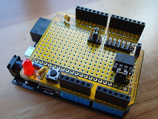
This shield was created to help learn SPI (Serial Peripheral Interface).  The hardware consists of an empty prototype shield for Arduino with a Microchip 25AA1024 EEPROM, jumpers, sockets, LED, switch, and discrete components.

This shield allows an microcontroller to store and retrieve up to 128K bytes of data using SPI at up to 20MHz speed.
The target platform was Microsoft .NET Micro Framework 4.1 as shown mounted on the Netduino Plus, and also demonstrated to work on the FEZ Panda IISource code for the project is posted at github in the form of a class library DLL and test application.  Note this code requires Microsoft .NET Micro Framework APIs and will not work on a standard Arduino.  Many others have written libraries for this chip for Arduino and other platforms.

The large array of jumpers allows configuration of the chip select line to one of digital pins 2-10.  The hold pin is pulled high and socketed to allow for future use, but is not wired to any of the microcontroller's pins.  The WP (write protect) pin is jumpered to allow it to be pulled high (disabled) or pulled low (enabled).  The circuit for the LED and reset switch was already present on the prototype shield.

A possible revision to this circuit would be to add a jumper for choosing 3.3V or 5V operation if it needs to be used with a board that is not 5V tolerant.  The boards I used run at 3.3V but are 5V tolerant. 

Future revisions to the source code could include supporting a wider range of EEPROMs from Microchip, SST, and other manufacturers, and/or porting the code to other platforms including mbed, chipKIT, PIC, and Arduino.


EEPROM Shield Schematic
Under belly of the shield