Showing posts with label m5stack. Show all posts

Saturday, August 15, 2026

Touch points and buttons on M5Core 2" displays, Tab 5" display, and Sunton 7" display for keyboard emulation


I have targeted the following M5 Stack models with my C64/C128/Vic-20/Apple 1 emulator:

(Even though I have targeted other boards, I had only implemented touch on the CoreS3)

The primary reason for targeting these boards was the common 2" 320x240 display perfect for most C64 emulation, and the availability of a wristband that works with Core2 and CoreS3 (it works with the Fire if and only if you never need to charge the battery - not aware of a universe where that works out long term).

[aside... Originally I had supported the M5 Core Basic, but without PSRAM, it was difficult to support the different computer models that currently load into that memory.  So M5 Core BASIC was dropped after its initial development.]

The Basic and Fire have three UI hardware buttons.   The Core2 has three virtual touchscreen buttons (touchscreen expands farther down from the LCD screen to allow for capacitive touch button points, and the M5 library abstracts them similar to physical buttons, so your code doesn't even have to know the difference).  The CoreS3 has no UI buttons, but I've manually implemented virtual touch screen buttons at the bottom of the screen.   From left to right the buttons are known to M5 as A, B, and C.

So button support for Basic, Fire, and Core2 was straightforward.

  • press Button A: Cursor UP
  • press Button B: RETURN
  • press Button C: Cursor Down
With hold functionality as well.
  • hold Button A: toggle computer model (C64, C128, Vic-20, Apple 1, repeats)
  • hold Button B: LOAD"*",8 / RUN for Commodore, snapshot system for Apple 1
  • hold Button C: STOP
Thus, one can demonstrate the emulator loading a menu of programs, scrolling though the listing, and choosing one.  And toggle between the emulators.   The Apple 1 snapshot system allows choosing a snapshot and loading or saving it.

I support other hardware targets, and I have BLE pairing functionality.  So I am thinking of expanding support of the virtual buttons, including more virtual buttons, and providing 8-position joystick inputs (and button) too.  But for now, here is the documentation for the existing buttons.

And then just like that, the CoreS3, Tab5, and Sunton 7" now have more touch points implemented for their capacitive touch screens to allow for more virtual keys.


Monday, June 29, 2026

Added Tab5 Keyboard support for my portable emulators for Commodore


Tab5 Keyboard is a convenience add-on

I added native keyboard support to my emulators already running on M5Stack's Tab5.

There were already 64/Vic-20/128 original keyboards, CardKB, web page adapter, Palm Portable Keyboard, and custom BLE support.  

Now there is also attached keyboard accessory support.  The Tab5 is a 5" ESP32-P4 handheld tablet with high resolution 1280x720 LCD.  The keyboard plugs into the bottom of the tablet, extending the size, and the capabilities.

The implementation scans all 70 keys for presses and translates to a list of C128 key scan codes into ASCII comma separated and newline terminated form, which the emulators already know how to translate into Commodore model specific keyboard scan codes.  As these are pressed scan codes, the press is persisted in the emulated system until the physical key is released.  These are symbolic mappings, not positional mappings because that is my preference.  Want different?  This is open source!

All visibly labeled keys are supported mostly as is.  Keys not Commodore specific are mapped to a Commodore PETSCII character already mapped to the proper ASCII character for the minimal environment (left arrow, underscore, caret, curly braces, pipe, backslash, backquote, tilde).  In addition, shift [Aa] supports letters, and numbers and punctuation to do the normal shifted characters.  Both [sym] and shift [Aa] do the symbols.   Additional keys worthy of documentation are:

  • _=             RIGHT SHIFT
  • tab            COMMODORE C=
  • sym tab        TAB
  • esc            STOP
  • shift esc      LOAD RUN
  • sym esc        ESC
  • ctrl sym del   STOP RESTORE
  • shift del      INSERT
  • \              £
  • sym shift \    SHIFT £
  • shift -        LEFT ARROW
  • sym shift -    SHIFT -
  • shift +        =
  • sym shift +    SHIFT =
  • sym shift *    SHIFT *
  • sym up         HOME
  • sym shift up   CLEAR
  • sym 1          F1
  • ...
  • sym 8          F8

As a reminder the emulators included are:

  • Commodore 64
  • Commodore 128
  • Commodore Vic-20
  • Environment similar to an Apple 1 (minimalistic 6502/6850/ROM/RAM plus terminal)

Links:

https://github.com/davervw/c-simple-emu6502-cbm/tree/unified-pio

Sunday, May 17, 2026

BLE HID Gamepad firmware for M5Stack MiniJoyC


It's not just another pretty face.  Time to get serious about retro gaming.  

Up, Left, Right, Down, Fire (M5) and second button (click joystick).  Not just a d-pad.  Is also mirrored as xpot, ypot, so can do paddle games, or analog joystick games.

Go play some games!

Link: github.com/davervw/m5_minijoystickc_gamepad

Also posted on M5Stack M5Burner

Sunday, September 8, 2024

Adafruit ST7789 TFT display with Arduino GFX Library and M5StampS3


Attaching a display to a circuit can provide a lot of detailed info and graphical value.  While "a picture is worth a thousand words," an animated display can be entertainment value, textual information can be informative, and add an input device, and the system can be interactive with billions of possibilities.

The tricks in embedded development is choosing the right display, having the right library that supports the display, and figuring out to use it all together with your target embedded system.

Shown above is a minimal footprint ESP32S3 in the form of an M5StampS3 from M5Stack connected to 2.54mm pins, with a rounded corner ST7789 based 280x240 display from Adafruit.  An SPI interface is utilized for communications using the GFX Library for Arduino.  I am using a solderless breadboard to prototype the circuit.  Later I will implement as a more permanent circuit.

Besides power and ground, there are only 4 connections from the ESP32: SCLK, MOSI, DC, and Reset.  In this sample, the TFT select line is permanently selected by connecting to ground.

(The Adafruit display used in this example also includes a MicroSD connector and SPI connections for that as well.  Support for SD is beyond the scope of this article, and would require additional changes to the circuit and code.)

#include <Arduino.h>
#include <Arduino_GFX_Library.h>
Arduino_DataBus *bus = new Arduino_HWSPI(1/*dc*/,
  GFX_NOT_DEFINED/*cs*/, 7/*sclk*/, 5/*mosi*/,
  GFX_NOT_DEFINED/*miso*/, &SPI, true/*is_shared_interface*/);
Arduino_GFX *gfx = new Arduino_ST7789(bus, 3/*rst*/, 1/*r*/,
  true/*ips*/, 240, 320);

void setup() {
  gfx->begin();
  gfx->fillScreen(BLACK);
  gfx->setTextColor(WHITE);
}

void loop() {
  int x = 20 + (int)random(280);
  int w = (int)random(300 - x);
  int y = (int)random(240);
  int h = (int)random(240 - y);  
  int color = (int)random(65536);
  gfx->fillRect(x, y, w, h, color);
  if (random(20)==13)
    delay(100);
}

The wiring corresponds to the code of the databus and gfx initialization parameters, specifically lines 1, 3, 5, 7 of the M5StampS3 connected to DC, RT (reset), SI (serial in), and CK (clock) of the display.  Also the displays V+ line is connected to 5V, and both TC and G (Ground) are connected to ground common to the ESP32 S3.

TFT   StampS3
V+    5V
3V    NC
G     Ground
CK    SPI Clock (7)
SO    NC
SI    SPI MOSI (5)
TC    Ground
RT    (3)
DC    (1)
CC    No Connection
BL    No Connection

It appears there is an overscan issue, beyond the rounded corners.  The gfx object is defining 320x240 display instead of 280x240, and the position and sizes of the rectangles are also interesting here.

Not sure why triangles are sometimes displayed (maybe out of range data?).  That is why there is a 5% chance of a tenth of a second delay to pause for the viewer.

This is just a demo.  You should be able to find much better uses for the display that these random rectangles.

Build details:
  • Arduino IDE 2.3.2
  • esp32 boards 3.0.4
  • GFX Library for Arduino 1.4.7

Friday, June 30, 2023

Extremely small emulated C64 and C128


This "portable" Commodore 64 and 128 emulator (m5 source code branch) is my work in progress, one in a series of minimalist emulators ported to different hardware targets. Only text (on LCD) with background, foreground, border colors, keyboard entry via USB serial tethered web browser, and general 6502/6510 and C64 memory management emulation is present (no, won't play games, make sound, or do bitmapped graphics) with some D64 emulation [added 7/2/2023].

(Update 7/28/2023) Now with GO 128 command.
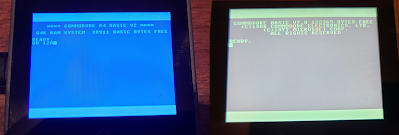
GO 128 command


Even my son asked, "Why do you need to do that?"  Well, he has a point.  I wanted a C64 that fit in my pocket or even on my wrist.  And targeting new hardware platforms with my emulator is part of my hobby.

How does it work?  Check out my highly technical drawing.

Now I already here you asking why I didn't connect Bluetooth to the M5Core, because certainly it has Bluetooth as well, and why didn't I use a USB keyboard connected to CoreS3, because it includes USB Host.  But I've had trouble tracking down examples of HID Host examples for M5; client examples are prevalent, but host?

Pictured here is a phone is running Chrome with a custom copy of the html/javascript keyboard adapter including web-serial-polyfill because mobile Chrome doesn't directly include Serial API support.  A Palm Pilot foldable keyboard has a Bluetooth adapter, paired with the phone.   HID keystrokes are captured by the web page, converted to C64 key scan codes, and a list of the active key scan codes (or 64 when keys released) is sent over USB Serial to the M5Core device which is running the C64 ROMs which are tricked into thinking a real keyboard is attached; keystrokes are processed by the C64 KERNAL IRQ as normal.

The M5Core is being powered by the phone.   Why M5Core?  Because it's a polished packaged solution.

Yeah, we could just run a Commodore 64 emulator on the phone, but this way, I could have complete control over the keyboard emulation, what keys are present, how CTRL and Commodore keys work, etc.  And it's just because I can, not because I should.

Why the Palm Keyboard?  Because it folds in my pocket!  And because I had one from back in the day.  Any keyboard you can attach to a phone or computer should work.  And this Bluetooth adapter just makes it so cool, and easier than a tethered keyboard.

The next step is to merge this solution with my Commodore 128 keyboard adapter to completely reject the portability feature.   That would look really cool hooked up to my phone!  Update (7/31/2023): check out YouTube for connection from ItsyBitsy/keyboard to Core Port.A.


C128 Keyboard Adapter Breadboarded Prototype
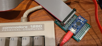

7/23/2023: PCB prototype keyboard adapter w/ ItsyBitsy

I am excited about my nonsense crazy adventures. Even if only I enjoy them.

=====

Update (7/2/2023): D64 support is currently working with Core2 only (Basic Core doesn't usually have the additional SPI RAM, but not yet sure why CoreS3 is failing to attach SD).

Update (7/3/2023): Got CoreS3 working with SD switching header to M5Unified.h for that target (was M5Cores3.h) and adding special definition, override logic for SD_CS to use GPIO_NUM_4 instead of default.  See updates to M5Core.h.

Update (7/28/2023): Commodore 128D extended keyboard working with UART connection to Port.A of Core, and Commodore 128 emulation is ported as well.

=====