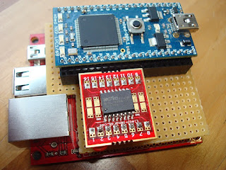
The "In-between Shield" has been developed as a means to extend the attached peripherals of the
mbed in a clean looking manner, inspired by the expandability of Arduino, but unique and true to the mbed experience.
This shield is designed to fit and work with the
workshop board for mbed. This is a a breakout board for Ethernet, USB, and SD for mbed. Instead of the mbed placed in the workshop board, the in-between shield is placed first, and the mbed sits on the shield. It should be possible to stack additional shields depending on the height of the components on each shield.
The shield itself is composed of a
solder breadboard cut to the dimensions of the workshop board, with an additional cutout to avoid the height of the Ethernet jack. I reduced this board's dimensions further so the USB ports can be visible from above. This visibility helps with attaching cables and devices.
 |
| workshop board |
 |
| In-between shield |
 |
| underside |
 |
Flash breakout boards
|
 |
| Above board shield in use |
The first in-between shield has two 8-pin sockets to accommodate a
16-pin SOIC breakout board with a flash chip attached (
SST25VF064C or
MX25L12835E). The flash breakout board can be easily changed out to attach different flash parts. Wiring beneath the shield connects the necessary pins back to the mbed. The mbed sits in two 2x20 wire wrapping sockets. No wire wrapping is used in this project. The advantage to the wire wrapping sockets is the extended leads so the shield sits above the workshop board.
The dual row sockets are used to extend the purpose of the workshop board: each side of the mbed sits in one row, and another row is provided for allowing jumper wires or a single above board shield. The rows of pins are not connected with the shield, it depends on their connections in the workshop board. If the workshop board is not available, a good substitute is another solder breadboard with two 2x20 sockets (short leads), with solder bridges between the pins.
 |
| Solder bridges |
The evolution of the flash shield included an ugly do it yourself SOIC to 2x4 pins breakout board made up from two separate 50 mils pitch boards, one for each side of the SOIC chip. An additional board was made to adapt dual 2x4 sockets to a single row 8-pin breadboard friendly connector, with LED to show power. The next iteration was an above mbed board using long single row headers that can be soldered to the bottom of a solder breadboard. Last but not least, the in-between shield was created.
 |
| First prototype and breakouts |
 |
| Above board shield prototype |
Source code for this project is posted
here. Driver for SST 64Mbit flash (8Mbyte) model 25VF064C including higher level methods for rewrite and buffered read/write to help optimize I/O. Can also work with other 25 series flash and eeprom devices, requiring minor revisions for their capabilities.
The end result of the in-between shield is a clean looking prototype of an mbed connected to a SOIC flash chip that can be further expanded.


No comments:
Post a Comment