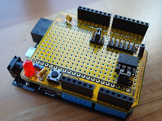
The large array of jumpers allows configuration of the chip select line to one of digital pins 2-10. The hold pin is pulled high and socketed to allow for future use, but is not wired to any of the microcontroller's pins. The WP (write protect) pin is jumpered to allow it to be pulled high (disabled) or pulled low (enabled). The circuit for the LED and reset switch was already present on the prototype shield.
A possible revision to this circuit would be to add a jumper for choosing 3.3V or 5V operation if it needs to be used with a board that is not 5V tolerant. The boards I used run at 3.3V but are 5V tolerant.
Future revisions to the source code could include supporting a wider range of EEPROMs from
Microchip,
SST, and other manufacturers, and/or porting the code to other platforms including mbed, chipKIT, PIC, and Arduino.
 |
| EEPROM Shield Schematic |
 |
| Under belly of the shield |


