Sunday, December 18, 2011

Individually Addressable and Dimmable Christmas Lights


This project was inspired by a Radio Shack print advertisement or similar article showing how to make a strand of Christmas lights using LEDs and an Ethernet cable connected to an Arduino controller.  I stole the idea and created the rest from scratch.


Christmas LED Shield
I found some large 1cm diameter LEDs that look like jelly beans at a local surplus electronics warehouse, and swapped out a black Ethernet cable that was in use in my house.  Having just completed assembly my Arduino Duemilanove kit, and being the middle of December, assembling Christmas lights seemed like the logical next project.  Originally I was going to place the LEDs 11 inches apart to use up the entire length of Ethernet cable, but my wife talked me into having them closer together, so after making cuts in the outer covering at 11 inches, I made additional cuts halfway between them, now every 5.5 inches. 

Curtain Rod Installation
The point of using an Arduino is addressing the individual LEDs.  As the Ethernet cable has eight wires, that could accommodate seven LEDs (seven lines of power, one common ground), so the original plan was to include seven and the Christmas Light Shield shown does support seven LEDs.  But the Arduino Duemilanove supports exactly six PWM (pulse width modulation) outputs at D11, D10, D9, D6, D5, and D3, so I settled on a six LED strand.  Each light can be individually dimmed to a resolution of 256 values (0=off, 255=bright).  This allows the lights to chase, flash, dim, and perform other light patterns.  Two inputs (in addition to reset) were added to the shield to control the nine patterns of the lights programmed into the Arduino.


The shield was built on a empty prototype PCB, with an attached RJ45 jack and corresponding breakout board.  The lines of the Ethernet jack were wired to the PWM ports using 500K resistors.  The switches were wired to inputs at D2 and D8 with 18K pull down resistors, and those circuits are wired to 5V when the switches are pushed.  The RJ45 jack turned out to be a great way to connect and disconnect the wires.

Merry Christmas!

Friday, December 16, 2011

Learning Surface Mount Soldering by Experience

Soldering together this Duemilanove (Arduino 2009 model) was my third attempt at surface mount soldering (first was FTDI232RL, second was PIC32). 

This was a roller coaster ride as it included a number of successes and failures.  Is it pretty? Not so much, but it works!  In the end it has been a success as the board works and I learned a lot. 
What exactly did I learn?

1. Dab some flux to the solder pads and tin them.  Heat the fluxed solder pad and apply a light coat of solder.  The flux and heat will suck the solder quickly so be careful to use little solder.

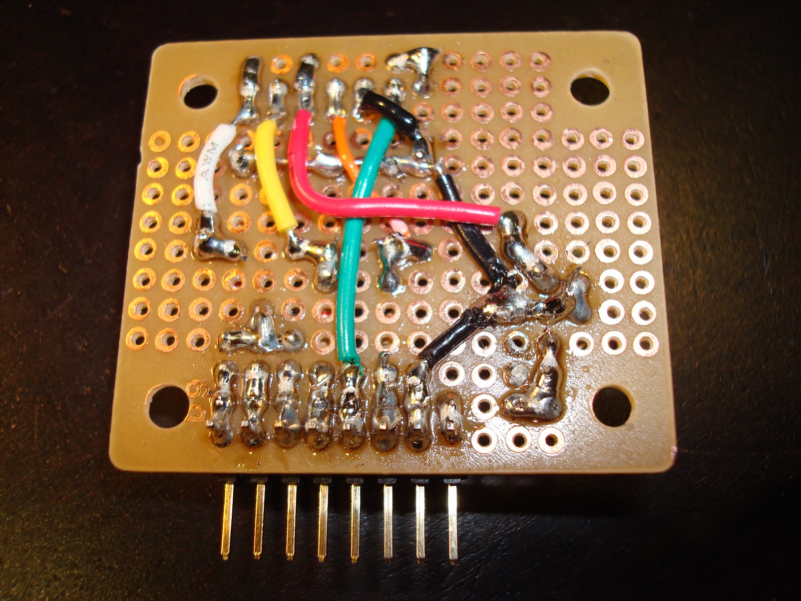
2. Use less solder, get the soldering iron hot enough, use a fine solder pitch, and a fine solder iron tip.  This board is a mess because I applied too much solder and many of the solders look horrible probably due to not enough heat.

3. Be careful desoldering.  I tried to clean up some messes with desoldering braid.  I wasn't very careful and tore off some solder pads.  This required three reworked lines.  You can easily see two, and a small one is in the top middle.  Using a continuity test mode of my multimeter and comparing a bare board with the board under test was very useful in isolating problems.

4. Order the right parts.  Double and triple check parts.  I ordered the bare Duemilanove PCB boards from Hong Kong via eBay, ordered most of the parts from Mouser, and some I already had on hand. 

But I ordered the voltage regulators in the wrong package size (8 pin instead of 3 pin), and ordered the corrected part from DigiKey.  But on the second try I had recorded a fuse part number for DigiKey, and ordered it blindly, and it turned out to be the completely wrong part - wrong value and wrong size.  I still don't have the right fuse.  And I never figured out the right diode.  It would probably take three or more orders to get the right parts.  In the end, I shorted the fuse and diode pads with bare wire, determining these are optional in this circuit design.  Also, I didn't realize I was out of USB sockets and had to purchase some locally. 

5. Order the correct quantity of parts.  I had three PCBs, and ordered most parts in quantity of five just to have extras.  For resistors and capacitors I ordered in quantity 100 to get the good price break and have extra stock on hand for future builds.  But the LEDs I bought only 10 and each board uses 4.  After losing one LED, and soldering one to a test board, I was short 4.  On my second parts order I splurged $8 to get another 100 LEDs.

6. I was able to use 20-pin breakaway sockets found at a local surplus warehouse to create the 8-pin and 6-pin sockets.  I had breakway sockets that already had indents per pin (not smooth), but those ones didn't match well with the standard ones.  Reading comments on SparkFun's site I learned that the standard sockets are created from the 20-pin ones even though they look smooth.  The only caveat is you lose one pin when you cut them (I used the cutter on my wire strippers), and if not done correctly you are unlocky and lose one of the pins you wanted to keep.  I was lucky this time.  Part numbers from DigiKey are also listed at SparkFun at the above link if you want them to cut them for you.

7. Reviewing the Arduino Duemilanove Eagle schematics and gerbers were indispensible for identifying parts and performing the assembly.  I was able to export the BOM from Eagle, but had to research most every part.  Also finding a high resolution picture of an assembled unit helped identify where to place the parts.

8. Soldering the FTDI part (FT232RL) was tricky to remember how to do it well.  It is a 0.65" pitch 28-pin device.  That's a lot of pins in a fairly dense package.  In the end, what worked best was dabbing just a tiny bit of solder on the tip of the iron.  Very very tiny dab.  And then applying the hot iron to the end of the fluxed pin.  Do every other pin, to let the hot solder cool before revisiting.  If I tried soldering consecutive pins or didn't have a steady hand, then the pins could short.  There still might be some shorts, but this design doesn't use every single pin, so I got away with a sloppy job again.

9. The Duemilanove can use an Atmel ATMEGA328-PU instead of an ATMEGA328P.  Since I ordered five CPUs, this saved me 68 cents per, or $3.40 total.  The difference internally is some additional low power idle statements yet doesn't appear required for Arduino programming.  To load these CPUs with the bootloader I had to follow some additional steps in addition to the standard tutorial on loading the bootloader.

10. Buying pre-built boards is much cheaper and efficient. It took me a week to build and test this, and multiple orders. Justing buying an existing board would have been much easier and cheaper.  But the experience is priceless.

11. I can do this!  Even with a cheap 30-watt Radio Shack soldering iron and a coil of lead-free solder.  Though I am considering purchasing a much higher quality iron.

12. Next step is to design my own PCB with a combination of through hole and surface mount components to balance physical size, price, and ease of build.  That will be another learning experience!


It works!  Shown with my thermometer board

Friday, December 2, 2011

USB PIC24 and PIC32 SPDIP Arduino

PIC24FJ64GB002 shown
Microchip has just released a SPDIP-28 PIC32.  This chip is pin compatible with the PIC24 which I have been developing for, and my latest toying has been with Arduino style boards, so I was determined to combine the two.

In the last week I have developed a prototype USB Arduino format board using a PIC24 or PIC32 as its CPU.  The Arduino format consists of the standardized 8 and 6 pin headers for I/O and power.  This was accomplished starting with an empty Arduino shield prototype board and building up as a PIC single board computer instead of a shield.  Now standard shields can be attached to this board.

The two CPUs I am targeting to support with this board are PIC24FJ64GB002 and the recently released PIC32MX220F032B.

The power circuit, ICSP (on left), and USB have been tested.  The PIC24 running a CDC (Serial over USB) project is recognized by the host PC.  Next step is to test the FTDI serial connector (on right), and all the analog/digital pins.  Following that is to add a crystal and capacitors to get USB support for the PIC32 (I wonder if I can do that on a shield?). All pins are exposed via the Arduino shield interface, so it is super expandable.  The red LED is for 5V power, and the green LED is for 3V3 power.  The button is the reset switch.  No user I/O are provided, must be accomplished by add ons.

The missing piece is the Arduino development environment support for PIC24 and this low end PIC32 chip.  That's a pretty big missing piece.  For now I can develop using Microchip's MPLAB 8 and MPLAB X.  I am hoping to use the chipKIT Arduino Development Environment for this board soon as it would be nice to program with Arduino sketches and C++. 
PIC32MX220F032B shown
Underbelly

Tuesday, October 11, 2011

Indoor/Outdoor Thermometer Shield for Arduino

This is a dual thermometer shield for Arduino.  It has ports for two temperature sensors (LM135, 235 or 335).   One sensor is local, and another can have an extended length of three conductor wire and encased in shrinkwrap tubing for weatherproofing.  The shield alternately displays the state of each of the temperature sensors in Fahrenheit. 

The temperature sensor portion of the circuit is tiny, less than a quarter square inch.  The majority of the circuit area is for the seven segment LED drivers.  The LED circuit includes 74HC4511 (one 7-segment led driver), 74HC138 (demultiplexer for led selection), and two 74HC04 chips (logic inverters).  Only one LED segment is lit at any one time, using interlacing it appears that all three are lit at once.  Using the 7-segment driver, only the digits 0-9 can be displayed, no negative numbers.

Voltage regulation is very important for this circuit, as a change in voltage will result in a change of reading.  Potentiometers are included for calibrating the sensors.

Headers are included for SPI and 5V power, to support a custom Ethernet adapter and custom SD card adapter.  Using pass-through connectors for supporting a shield on top of this one was not a priority.  A jumper is provided for running the circuit at 3.3V, but 5V operation is preferred for LED brightness; and due to the 74HC chips, the logic is compatible with any 3.3V Arduino that can source 5V power.  This shield was built on a ProtoShield and has been successfully tested with the 5V Diavolino (Arduino Duemilanove clone), 3.3V chipKIT Max32, and 3.3V GHI Electronic's Panda II.


Shield working with PIC32 based Max32
Now logging to SD card with Panda II board

Monday, September 19, 2011

Car Alarm

This summer an opportunistic small time thief has been roaming our neighborhood stealing ipods from unlocked cars.  To discourage them messing with our vehicles, I built this circuit and installed it in my wife's car.  We use a rechargable 9V battery and recharge/replace it about every two days.  This project was fast to develop and satisfying to see in action.


Build #2 with battery inside

Wednesday, September 14, 2011

LED Bar

In bread boarding a micro controller circuit, one of the most popular components is an LED.  Light up an LED to indicate power connected, turn it on or off based on a mode change, or flash an LED to indicate the CPU is working.  Because LEDs are typically rated for less current than a CPU or power supply can provide, they require a current limiting resistor to keep them from burning out. 


One of my tasks in learning about new processors, is to see if I can configure every line as an output port, and if I can run the CPU at its maximum speed.  I set up an integer counter in my code, and bit shift the value into all the output lines I care about.  Using this LED bar, I can insert it into the breadboard next to the CPU pins, flip the switches off to lines I don't want to bother or mess with (like crystals, voltage regulator configuration, USB lines, etc.) and if everything works out right, watch the lights blink on and off in binary code.

The LED bar has nine LEDs in a row encased in green plastic, with 18 pins (upper pins are the cathode and the lower pins are the anode).  Nine current limiting resistors connect the cathodes to ground through eight switches.  The rightmost LED is used to indicate power and bypasses the switches; the jumper in the upper right is the ground (top) and power (bottom) connections.  These components are placed on a mini circuit board with pins so it can sit upright on a breadboard.


Saturday, September 10, 2011

microSD Arduino adapter

Arduinos are meant to be attached to peripherals.  Here is an adapter from a 5V Arduino to a 3.3V microSD card.  To bridge the gap from circuit board to SD card, a socket is used to connect a microSD breakout board (BOB).  Resistor voltage dividers bridges the gap between the voltage differences for outputs.  A low dropout voltage regulator supplies 3.3V power for the SD card.  Inputs from the SD card are within spec for the Arduino, so they did not have to change.

This adapter is a vertical shield.  It has a socket so the pins are accessible if the attachments are compatible.  It only connects to the AREF to D8 eight position socket, which does not have power, so it requires a jumper from 5V(VCC) to one of the slots on its dual socket, so as to replace the 5V socket with another one.  It also has a 1 port card detect (CD) socket, which can be jumpered to another available pin on the Arduino.

It is modeled to support the SD CardInfo example included in the Arudino IDE.  Chip select (CS) is connected to D8 with a jumper, it can be moved to D9 or D10.  It can be used simultaneously with the Ethernet non-shield.


5V Arduino SD Adapter Schematic

Tuesday, September 6, 2011

My own first PIC32 Development Board

Here is a USB PIC32 development board that is in progress.  I bought a bare 64-pin PIC32MX795F512H which is the highest end Microchip 32-bit CPU, except for having 36 fewer pins pins than its close sibling.  This CPU has 512K Flash, 128K RAM, and runs at 80MHz.

It was soldered to a breakout board that is connected by dual row 0.1" 16-pin headers so it can be mounted in sockets on a standard solder breadboard.  It has three symmetrical 8 pin headers which expose shared SPI/UART (total of 6 RX/TX pairs), and power lines.  Jumpers choose between USB host and USB device functionality.
The first test of this board was as a four port RS-485 monitor.  I was able to enhance the monitor's protocol to support four sources, then enhanced it as a bidirectional adapter.  The code is built on Microchip's USB device CDC sample and shared among various PIC targets, so the code is also supported on other various 8-bit and 16-bit PICs too.

A planned test is to breakout the RMII/MII lines to an Ethernet PHY and test the Ethernet capability of this CPU.  I purchased a QFN 36-pin SMSC LAN8700 PHY but unfortunately I cannot find a compatible breakout board for it.  Nine pin sides seem to be an odd number, and the breakouts I have tried are built for even numbered pins per side making this one just a bit too small to work with the traces.  My next plan is to try a QFN 24-pin SMSC LAN8720 PHY.

Another plan is to get it to work with the chipKIT Arduino-Compatible Prototyping Platform so it can be programmed in C++.

Monday, September 5, 2011

Arduino Ethernet Shield without the Shield

This project adds Ethernet to an Arduino.

I had already purchased the WIZ811MJ module, and crafted the W5100 SPI module which essentially has the components of a basic Arduino Ethernet shield without SD support. After recently aquiring an Arduino Duemilanove clone, the Diavolino, I used jumper wires to connect the two, but it was too messy. Using solid wire soldered to female headers, and one stray connector wire, I resulted in a cleaner solution. The ethernet module runs on 3.3V but this Arduino runs on 5V, so a voltage regulator circuit was necessary, and ended up soldering it right to one of the headers along with support capacitors (a cleaner look would involve shrink wrap tubing). The W5100 tolerates 5V inputs and the 3.3V outputs are accepted correctly by the Arduino, so no signal voltage translations were necessary. I successfully tested this adapter cable with the Arduino example Ethernet telnet client. 

The entire adapter
Angled perspective

View with Voltage Regulator

Saturday, September 3, 2011

Serial Text LCD

Serial Text LCD module
This project connects a Text LCD display to a microcontroller or PC via a single serial transmission line (plus power).
One of the challenges of integrating a text LCD display is the number of pins to connect. A display module typically has 16 lines, with 11 for data and control. That's a lot of lines for a microprocessor to handle. One way to handle it is to get an I/O expander (I2C or SPI), another way is to use a serial protocol such as a UART. The advantage of have a UART compatible text LCD display module is that it can be controlled with just a single TX line. The downside is using up one of (or your only) microcontroller's UART transmission line, unless you can use software UARTs.

backside
Prototype with serial connections

My requirements included performing a very simple firmware implementation.  I didn't want to spend a lot of effort creating the module.  And I wanted to learn the communications with the LCD module, so limiting to just a text interface was not desired.  I ended up implementing a 6-bit raw protocol, and writing a .NET program to talk to the LCD using 4-bit mode.  I already had some firmware for my 485 monitor that I quickly adapted for use with the LCD.  Bytes are received serially on the RX line, then output to the PORTB, of which 6-bits are wired to the LCD.  After echoing the raw hex back on the TX line (for diagnostics, not necessary for operation), the data byte is strobed with bit 5 cleared to finalize communication with the LCD.  I ended up expanding on the .NET program to have a form where what is typed on the screen is efficiently updated to the LCD screen.

I want to interface with 3.3V microcontrollers, and I want the cost to be low, so I used an available PIC18F26K22 I had received as a sample from Microchip, with the circuit using 5V from USB stepped down to 3.3V with a voltage regulator for the CPU.  The LCD runs at 5V, accepting 3V logic from the CPU.  The latest version of the circuit has an added jumper to select whether the PIC runs at 3.3V or 5V, which in turn determines the I/O voltage levels of the module.  The five port socket includes 5V, 3.3V (output), Ground, TX (output), and RX.  Minimally only 5V, Ground, and TX need to be connected.  This PIC is currently configured to run at its top speed of 64MHz! (This may be overkill for just driving an LCD.)  The LED in the circuit is a heartbeat to show that the PIC is running.

.NET program and hex diagnostics 
Schematic


I plan to immediately use this module with other PIC, Arduino, and Netduino projects.  Writing the .NET program allowed me to more easily learn the LCD protocol than debugging the firmware.  I may expand the firmware to move more of the LCD protocol into the PIC18 firmware, or at least have that option.  Other possibilities are to implement I2C and/or SPI interfaces.

Update: In addition to Windows, I have had success using this module with the mbed, LPCXpresso 1769, chipKIT Max, and Arduino. 

Monday, August 8, 2011

mbed Text LCD development board


This is my take on an mbed development board to support different LCD sizes.


The three sizes shown here are 20x4, 16x2, and 8x2.  Some LCD screens have a single row of 16 pins.  Others have two columns of seven (or eight) pins.  I developed this board to not hard-wire any connections except those dedicated on the mbed itself.  The LCD screen can be wired up in 4-bit (shown) or 8-bit mode using any available I/O lines.  Additional sockets are provided for USB host, USB device, Ethernet MagJack, and microSD.  Four switches with sockets are also provided.


eBible with power from Motorola


As most everything was socketed and not hard-wired, there's a lot of solder bridges connecting the sockets.  14 or 16 of the LCD socket connections are wired together in a mass of wire under the board.  This allows using jumper wires for just the top 16 wire socket, and plugging in any of the three LCDs that I have.  One of the LCDs was modified to grab power from the 2x7 socket.  Another has an additional two leads that are socketed.  The reason for the two different 2x7 sockets was that the functions of pins 1/2 were reversed on the 16x2 LCD display.  Alternatively, I could have used a switch or relied on changing the jumper wires.

The microSD has 7 connections, so just provided a 7x2 socket, and this requires jumpering the lines to the mbed.  I can then choose which SPI connections to make, and what line to be the chip select and/or card detect.  I attach a microSD breakout board from SparkFun.

The Ethernet MagJack is hard wired except for the LEDs.  A specific breakout board from SparkFun is required.

A USB device jack is socketed to support a mini USB device breakout board.  Alternatively a USB-A cable can be connected.

Power (3.3V) and ground buses are included, hard wired to the mbed.

Wednesday, August 3, 2011

PIC24 USB + Serial Development Board


Two main emphasis of this board are USB and Serial as well as using socketed components.  The 28-pin PIC24FJ64GB002 can perform as either a USB host or USB device, using jumpers to select between the connected USB socket.  The USB jumpers are also configured so when the PIC is USB host using the USB-A connector to attach a thumb drive, the USB-B connector may be configured to attach to an FTDI FT232RL chip to act as USB serial.  Using a USB-A to USB-B adapter, both the PIC and the FTDI chips could be active as USB devices. 

Two serial channels are jumpered for either RS-485 or RS-232 (DB-9 connectors not shown), or the second serial channel can be jumpered to the FTDI USB serial connection.  As configured here, RS-485 uses RX/TX with RTS to select whether reading or writing.  RS-232 can use RX/TX with CTS/RTS.  The ICSP (in circuit serial programming) connection in the lower left works with ICD or PICKit programmers, and shares the lines that provide CTS/RTS, so jumpers are provided to choose between those functions.  The PIC24 has quite a few 5V tolerant inputs, but I ran out of enough of them, so a 5V/3V3 logic level conversion board is socketed to read the CTS lines at 3.3V from the 5V MAX232 and MAX233

Voltage regulators are included to power 3.3V and 5V buses, accepting power from USB or 7V-12V external power.  Each module has a power jumper to effectively disable them.  The USB sockets have jumpers to selectively attach power to the 5V bus.

One SPI channel is also configured, allowing connection of features such as a micro SD card and/or SPI Ethernet.  This board specifically supports connection of a Microchip's PICtail Ethernet (ENC28J60) board.